Do you have a question about the Hasbro Tomy Zoids Chimera Dragon and is the answer not in the manual?
Illustrates the connection of parts C08 19, C08 20, D08 24, D08 25, and J9 to form the head.
Diagram showing assembly of parts B08 9, B08 10, D21, and B08 12.
Diagram showing assembly of part B26.
Illustrates connecting leg components B06 9, A02 2, C06 14, C06 16, C06 17, B06 12, and J02 1.
Illustrates connecting leg components B06 8, A06 1, B06 13, C06 15, and J02 1.
Shows attachment of parts C08 17, C08 11, and D08 22 with ring caps.
Illustrates attaching ring caps to parts B05 3, D08 14, and A08 5.
Shows attachment of parts C08 18, C08 10, D08 23 with ring caps.
Illustrates attaching ring caps to parts B05 4, D05 15, and A06 6.
Assembly of left and right wing structures using specified parts.
Connecting wing components with ring caps.
Connecting the right wing assembly to the main body using J2 and D05 18.
Connecting the left wing assembly to the main body using J2 and D05 19.
Assembly of parts B07 6, B07 7.
Assembly of parts C08 16, C08 15, and J9.
Assembly of parts B07 9, B07 8.
Assembly of parts B08 14, B08 13.
Attaching parts B07 7, D17 17, C05 8, C05 9, D05 16 to main body.
Connecting components C07 5 with ring caps.
Connecting components C07 14 with ring caps.
Illustrates connecting jaw components using parts J3 and J8.
Connecting main body parts using J8, J6, and A08 3.
Illustrates connecting tail components using J6 and J8.
Shows attachment of main body sections using J6.
Shows final attachment of head and leg assemblies to the main body.
Illustrates the process of attaching the left leg assemblies to the main body.
Illustrates the process of attaching the right leg assemblies to the main body.
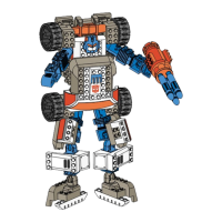
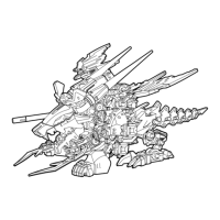
Shows the fully assembled model.
Advises against holding the model by the tail or indicated parts.
Warns against applying excessive force to move the model.
This document outlines the assembly and features of a model kit, likely a robotic or creature-like figure, referred to as a "Zi-builder." The manual emphasizes a user-friendly assembly process and provides guidance on handling the completed model.
The primary function of this kit is to allow users to construct a detailed model. The completed model appears to be a multi-legged, winged creature with a distinct head, tail, and various articulated parts, suggesting it is designed for display and potentially limited posing. The inclusion of "Runner Frame J parts" being identical across "Zi-builders TM kits" implies a modular system, where parts can be interchanged or combined with other kits from the same series, expanding the creative possibilities for builders. The labels provided with the kit serve an aesthetic function, allowing users to customize the appearance of their completed model.
Assembly Process: The kit is designed for "easy snap-together fit," eliminating the need for glue, which simplifies the assembly process and makes it accessible to a wider range of users, including those new to model building. The instructions stress the importance of reading the entire manual before starting assembly to ensure a smooth building experience. Parts are organized by lettered frames and numbered parts, with each individual part also marked with its specific number and letter. This systematic labeling helps users identify and correctly assemble the components, reducing the likelihood of errors.
Part Handling: Users are instructed to remove plastic parts from their frames according to the instructions. For removing excess plastic, the manual recommends using scissors or another suitable tool, indicating that some trimming may be necessary for a clean finish. This attention to detail in part preparation contributes to the overall quality of the assembled model.
Disassembly and Customization: A notable feature is that the kit "can be disassembled if necessary." This allows for corrections during assembly, modifications, or even storage. The ability to disassemble also supports the modular nature of Zi-builder kits, enabling users to reconfigure their models or integrate parts from other kits. Once the kit is completed, users can "apply the labels anywhere you like," offering a degree of personalization and aesthetic customization to the final product.
Extractor Tool: The manual introduces an "Extractor Tool" designed to "loosen tight joint parts." This tool is a practical addition, addressing a common challenge in snap-fit models where joints can become too tight, making disassembly difficult or risking damage to parts. However, the manual also notes that the "Extractor may not loosen some joints," indicating that while helpful, it might not be universally effective for all tight connections. This provides a realistic expectation for users regarding the tool's capabilities.
Handling the Completed Model: Specific instructions are provided for handling the completed model to prevent damage. Users are advised "Do not hold by tail or other parts indicated in the illustration" and "Do not force model to move." These warnings highlight delicate areas of the model and emphasize the importance of gentle handling to maintain its structural integrity and appearance. The illustrations visually reinforce these handling precautions, showing a hand gripping the tail with a "Do not hold" arrow, and arrows pointing to various parts of the model that should not be used for support or movement.
Initial Preparation: The manual implicitly includes maintenance features by guiding users on proper initial preparation. Trimming off "any excess plastic" when removing parts from frames ensures that the assembled model has a clean finish and that parts fit together correctly, preventing future issues that might arise from poorly prepared components.
Storage of Instructions: Users are advised to "Save instructions for future reference." This is a crucial maintenance feature, as the instructions contain vital information for reassembly, troubleshooting, or understanding the model's structure if repairs or modifications are needed later.
Disposal of Packaging: The instruction to "Discard plastic bags immediately" is a safety and organizational feature, preventing clutter and potential hazards, especially for children. While not directly related to model maintenance, it contributes to a clean and safe building environment.
Disassembly for Repair or Modification: The ability to disassemble the kit serves as a key maintenance feature. If parts become damaged or if the user wishes to modify the model, the option to take it apart allows for easier access to internal components for repair or replacement. This extends the lifespan and versatility of the model.
General Care: Although not explicitly stated as maintenance, the warnings against holding the model by delicate parts or forcing its movement imply a need for careful handling to prevent breakage. This gentle approach is a form of preventative maintenance, ensuring the model remains in good condition over time. The labels, once applied, are likely permanent or semi-permanent, so their placement should be considered carefully, as repositioning might damage them or the model surface.
| Product Line | Zoids |
|---|---|
| Motorized | Yes |
| Product Name | Chimera Dragon |
| Category | Toy |
| Type | Model Kit |
| Material | Plastic |
| Manufacturer | Tomy |
| Series | Zoids |