Do you have a question about the Haulotte HA 41 PX and is the answer not in the manual?
Information on manual usage, labels, and general safety precautions.
Guidelines for operator age, environment, and machine usage.
Details on potential dangers like jerky movements, electrical hazards, and collisions.
Requirements for periodic, suitability, and conservation inspections of the machine.
Procedures for major repairs, adjustments, and pre-service checks.
Table relating wind descriptions to speeds for operational safety.
Details on identifying the machine, including its plate and serial number.
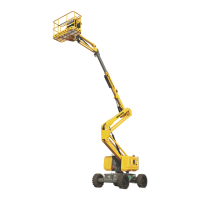
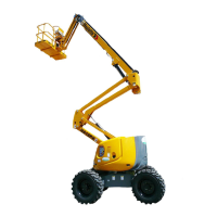
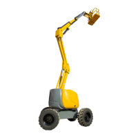
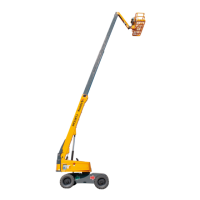
Identification of major physical parts of the Haulotte HA41PX machine.
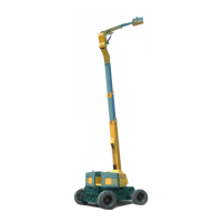
Graphical representation of the machine's operational envelope and reach capabilities.
Detailed specifications including dimensions, weight, power, and capacity.
Explanation of the hydraulic system's role in machine movements and functions.
How the platform maintains level and adjusts for arm/jib movements.
Details on the linkage that maintains arm/jib parallelism and compensation.
System for extending the chassis and axles for stability and operation.
Electric system overview and safety measures for machine operation.
Essential safety precautions during machine operation and deployment.
Procedures and precautions for safely handling and transporting the machine.
Steps and checks required before the machine's initial use or after storage.
Procedures for starting up and preparing the machine for operation.
Procedures for safely descending the platform in emergency or breakdown situations.
Guidelines for performing maintenance operations safely and effectively.
Overview of maintenance points, frequencies, and required tools.
Detailed list of maintenance tasks based on frequency, including checks and greasing.
Requirements and procedures for overload, functional, and stability tests.
Troubleshooting for engine stoppage causes and solutions.
Troubleshooting for incidents causing lack of platform movement and error codes.
Resolution for various operational issues like turret or lateral movement problems.
Identification and function of relays and fuses in the turret cabinet.
List and description of safety sensors and switches used in the machine.
First part of the electrical schematic diagram of the machine.
Second part of the electrical schematic diagram, covering specific circuits.
Third part of the electrical schematic diagram, detailing various control signals.
Fourth part of the electrical schematic diagram, showing sensor inputs.
Fifth part of the electrical schematic diagram, illustrating control solenoids and pedals.
Sixth part of the electrical schematic diagram, showing axle and chassis sensors.
List of electrical components, their references, and related diagram folio numbers.
First sheet of the hydraulic system schematic, detailing main circuits and cylinders.
Second sheet of the hydraulic system schematic, showing pumps and motors.
Third sheet of the hydraulic system schematic, illustrating steering and blocking functions.
List of hydraulic components referenced in the diagrams.
| Brand | Haulotte |
|---|---|
| Model | HA 41 PX |
| Category | Lifting Systems |
| Language | English |