If horn sounds in flight, it may be
muted by depressing APU FIRE
switch, and will cease sound if tem-
perature condition draws below
alarm point.
Main DC Generator Failure
Do not start APU if both main engine gener-
ators have failed. If both engine generators
have failed and the APU is already operating,
the APU may be left on provided the APU
generator is operating. Follow emergency pro-
cedures in the basic Airplane Flight Manual
for two main generators inoperative.
A failed APU start with two inoper-
ative main generators may deplete
the aircraft batteries and leave the
aircraft without electric power.
TURBOMACH APU
(T62T-40)
GENERAL
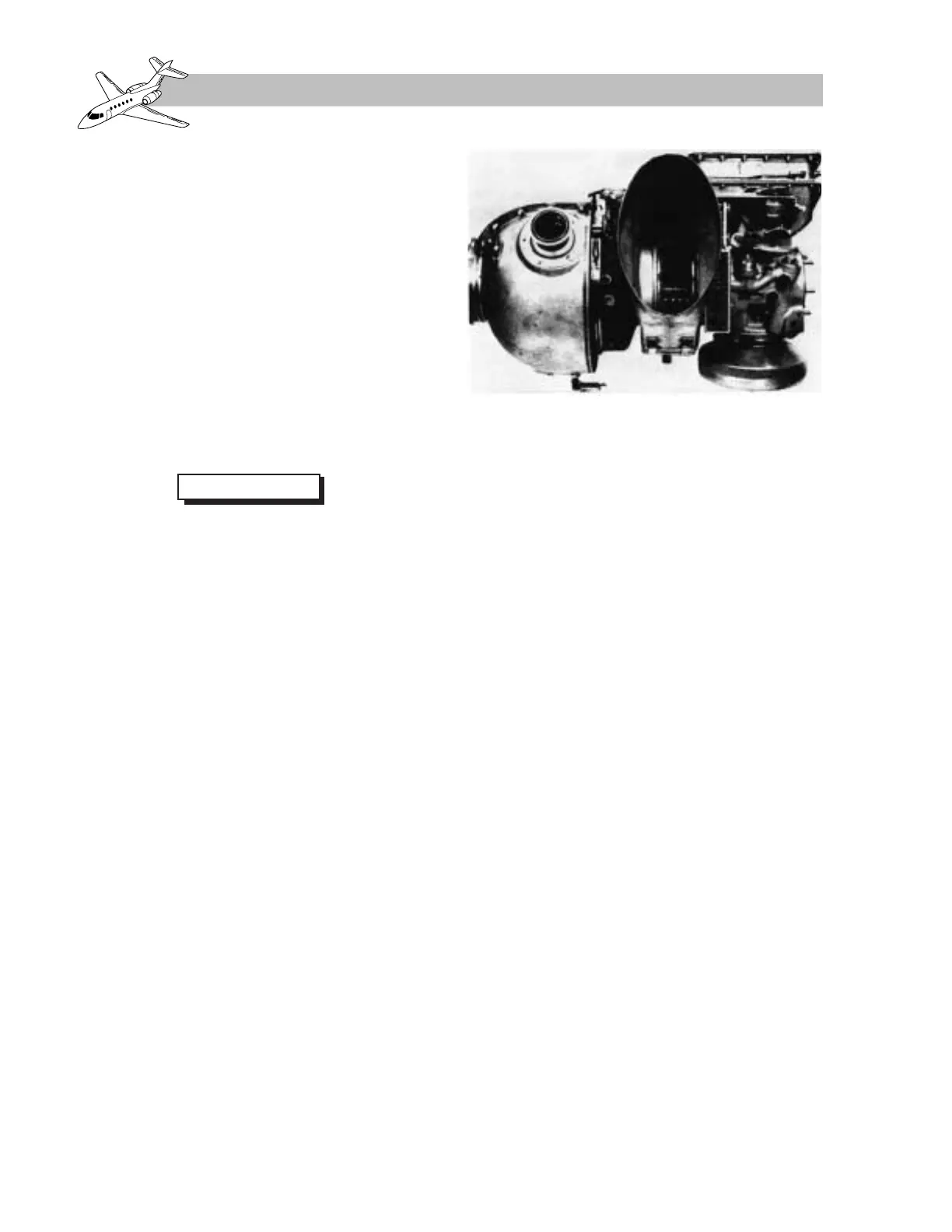
The Hawker 800 XP series may be equipped
with an APU (Figure 6-3) manufactured by
Solar Turbines International. This APU is des-
ignated T62T-40. The turbomach APU is cer-
tificated for both on-ground and in-flight (for
emergency use only) operation. Flight oper-
ation is limited to a maximum altitude of
15,000 feet (emergency only).
MAJOR SECTIONS
The Solar APU (Figure 6-4) is a small gas tur-
bine engine consisting of six major sections:
1. Air inlet
2. Compressor
3. Combustor
4. Turbine
5. Exhaust
6. Reduction drive assembly
Air Inlet
The air inlet is a screened, circular opening in
the waist of the APU, and it provides the main
air inlet to the compressor.
Compressor
The compressor is a single-stage centrifugal
impeller which draws air through the inlet,
compresses the air, and directs the airflow for
cooling combustion and bleed-air extraction.
Combustor
The combustor consists of a shrouded, re-
verse-flow annular chamber supplied with a
specific air volume from the compressor. Fuel
is added to the combustion air by a start fuel
injector and three main fuel injectors, each
controlled by a solenoid valve. In addition, a
maximum fuel solenoid valve increases fuel
flow to the main fuel injectors during high
load periods.
Ignition is supplied by a single igniter plug.
 Loading...