EasyManua.ls Logo

Haworth Upside - User Manual

Haworth Upside
20 pages
Print Icon
To Next Page IconTo Next Page
Loading...
Height-Adjustable Table
For assembly assistance, visit Haworth.com, or call: 1-800-426-8562, or email support@haworth.com
Upside
Assembly Instructions
Congratulations on
your purchase of a
new Upside table!
Ready to put some movement into your day?
We know you want to get up and running as soon as possible, but
before you dive right into setting up your table, be sure to:
1. Grab a friend to help you with the lifting. They can also help you
hold parts in place during assembly to make things a little easier.
2. Make sure you have all your parts and hardware, and gather the
necessary tools and safety equipment.
3. Follow all the steps and synchronize your table before using it.
That's it! Once you've got your table assembled and synchronized,
you'll be ready to enjoy the freedom to change position as you work
anytime you want.

Other manuals for Haworth Upside

Question and Answer IconNeed help?

Do you have a question about the Haworth Upside and is the answer not in the manual?

Summary

Important Safety Instructions

Electrical Safety and Grounding Precautions

Crucial warnings regarding electric shock, grounding, and proper electrical connection for safe operation.

General Operational and Usage Warnings

Essential safety guidelines for operating the table, covering burns, fire, injury, and proper usage.

Attaching Leg Columns to Support Frame

Attaching Support Brackets to Leg Columns

Securing Frame and Bracket Connections

Mounting the Assembled Frame to Worksurface

Aligning Frame Brackets with Worksurface Holes

Aligns frame support brackets (B) with pre-drilled holes in the worksurface (A) for attachment.

Securing the Frame to the Worksurface

Installing Worksurface Attachment Screws

Installs four screws (S201) to securely attach the frame assembly to the worksurface.

Attaching Feet and Stabilizing Set Screws

Control Box and Motor Cable Connections

Connecting Motor Cable to Control Module

Plugs the motor cable (D) from the leg columns into the control box (F).

Mounting the Electronic Control Box

Installs the control box (F) onto the worksurface, considering frame width for placement.

Connecting Power and Extension Cables

Installing Handset and Cable Management

Final Assembly and Leveling Procedures

Table Synchronization Process

Initial Table Descent for Synchronization

Lowers the table to its lowest position using the paddle handset as the first step.

Performing the First Synchronization Hold

Presses and holds the paddle handset for 15 seconds to initiate the motor synchronization.

Completing the Synchronization Adjustment

Presses and holds the paddle handset until the table slightly moves upward for final sync.

Synchronization Intervals and Calibration

Required Synchronization Triggers

Details necessary synchronization events: initial use, after disconnections, and monthly checks.

Overview

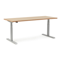
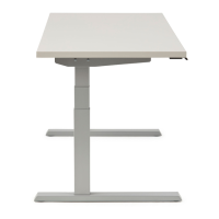
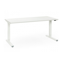
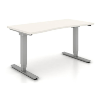
The Haworth Upside Height-Adjustable Table is an electric height-adjustable table designed for commercial or household use. It conforms to UL962 and is certified to CAN/CSA C22.2 No. 68, ensuring safety and quality standards.

Function Description:

The primary function of the Upside table is to provide a customizable workspace that allows users to easily switch between sitting and standing positions throughout the day. This is achieved through an electric height-adjustment mechanism controlled by a paddle handset. The table is designed to promote movement and ergonomic flexibility in the workspace.

Important Technical Specifications:

  • Electrical Rating:
    • Upside Standard 2-leg tables: 120V, 60Hz, 6.25A
    • Upside Value 2-leg tables: 120V, 60Hz, 6A
  • Grounding: The product must be properly grounded to reduce the risk of electric shock. It is equipped with a cord having an equipment-grounding conductor and a grounding plug, which must be plugged into an appropriate, properly installed, and grounded outlet.
  • Maximum Load Rating: The table can support a maximum load of 250 lbs, including the surface.
  • Components: The table consists of a worksurface (A), end brackets (B), a paddle handset (C), leg columns (D), feet (E), a control box (F), a power cord (G), a frame (H) with rails (H1), motor extension cables (J), and cable clips (K).
  • Hardware: Various screws are used for assembly, including M6x10mm Button Head screws (S200), M5x20mm Truss Head screws (S201), M5x16mm Truss Head screws (S202), M4x30mm Pan Head screws (S206), M6x14mm Button Head screws (S209), and M6x8mm Set Screws (S-90).
  • Tools Required for Assembly: Drill, 1/8" drill bit, tape, level, #2 screwdriver, 13mm wrench, 3mm Allen wrench, and 4mm Allen wrench. Casters are optional and require a 13mm wrench for installation.

Usage Features:

  • Height Adjustment: The table's height is adjusted using a paddle handset (C).
  • Synchronization: The table motors must be synchronized before first use, monthly to maintain synchronization, after any power interruption, and anytime a cable, plug, or paddle is plugged into the control box. This ensures proper and coordinated movement of the legs.
  • Safety Precautions:
    • Always unplug the furnishing from the electrical outlet before cleaning or servicing.
    • Unplug from the outlet before putting on or taking off parts.
    • Close supervision is necessary when used by or near children, invalids, or disabled persons.
    • Use only for its intended purpose as described in the instructions.
    • Never operate if the cord or plug is damaged, if it's not working properly, or if it has been dropped, damaged, or dropped into water.
    • Keep the cord away from heated surfaces.
    • Do not use outdoors.
    • Do not operate where aerosol (spray) products are used or oxygen is administered.
    • To disconnect, turn all controls to the off position, then remove the plug from the outlet.
    • Ensure appropriate critical components and accessories are used during assembly to prevent electric shock, fire, and injury.
  • Assembly Assistance: Haworth recommends having a friend assist with lifting and holding parts during assembly.
  • Optional Casters: Casters (D2) can be installed for mobility, replacing the standard foot pads (D1). These are ordered separately.
  • Control Box Placement: For frames less than 46 inches wide, the control module (F) must be mounted outside the frame (H). For 52 inches and larger frames, it can be mounted within the frame.

Maintenance Features:

  • Cleaning and Servicing: The table must be unplugged from the electrical outlet before any cleaning or servicing.
  • Synchronization Intervals: Regular synchronization is crucial for maintaining calibration and proper functioning. This includes:
    1. Before first use.
    2. After any cables/cords are disconnected/reconnected or after servicing any component (e.g., swapping out paddles, disconnecting/reconnecting cables/cords).
    3. After any interruption in power or loss of power (or any time the power cord is unplugged from the outlet and plugged back in).
    4. Monthly to maintain optimum table performance.
  • Troubleshooting Synchronization: If the table does not move up or down during synchronization, specific steps are provided, including holding the paddle for longer durations or unplugging and replugging the table after a waiting period.
  • Paddle Handset Installation: The paddle handset (C) should be installed with a hand screwdriver ONLY, ensuring screws (S206) are installed straight and fully seated to prevent interference with performance.
  • Cable Management: Cable clips (K) are provided to help organize and secure cables, contributing to a tidy and safe workspace.

Haworth Upside Specifications

General IconGeneral
BrandHaworth
ModelUpside
CategoryIndoor Furnishing
LanguageEnglish

Related product manuals