ELECTRONIC BRAKE
CONTROLLER
HAYES BRAKE CONTROLLER
COMPANY P/N 81725
OPERATION MANUAL
For trailers with 2 or 4 electric
brakes and vehicles with 12 volt
negative ground systems only.
READ AND SAVE THESE
INSTRUCTIONS
•Before beginning operation, read and
become familiar with these
instructions.
• Leave in tow vehicle for future
reference.
•Improper installation and
operation could cause personal
injury and/or equipment and
property damage.
• Questions on installation, adjustment,
troubleshooting, or operation of brake
controllers
• Call 800-892-2676 Monday
through Friday between 8:00 a.m.
and 5:00 p.m. EST.
SAFETY INFORMATION
WARNING: Indicates a
potentially hazardous
situation that, if not avoided,
could result in death or
serious personal injury.
CAUTION: Indicates a
potentially hazardous
situation that, if not avoided,
could result in damage to
product or property.
TIP: Contains helpful
information to facilitate
operation
.
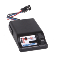
SYNCRONIZER
The automatic mode modulates and
controls the current from the battery to
the trailer brakes and operates on a
time-based circuitry. The longer the
brake pedal is depressed, the greater the
current delivered to the trailer brakes.
The current will increase until it reaches
the preset brake power adjustment
setting.
Automatic Operation
Power Wheel Adjustment
(for Automatic Braking only)
• The “Power Wheel” (Figure 1) is
located on the front left side of the
controller.
• The Power Wheel is used to adjust
the amount of current to the trailer
brakes. It is responsible for obtaining
smooth, proportional, and optimum
tow vehicle and trailer brake
responsiveness.
• To increase the amount of current,
rotate the power wheel upward
toward the top of the case.
• To decrease the amount of current,
rotate the power wheel downward
toward the bottom of the case.
WARNING:
• Improper adjustment of the
controller could result in loss of
trailer brakes, aggressive, grabby,
pulsating, or delayed trailer
brakes.
• Power adjustments may be
required based upon speed, trailer
load, and road conditions.
•Maximum trailer braking occurs
just prior to lockup of the trailer
wheels.
•Trailer brake lockup could cause
loss of control of the trailer and/
or the tow vehicle.
Manual Slide Lever
Operation
• The “Manual Slide Lever” (Figure
1) is located on the front right side of
the controller.
• The further the manual slide lever is
moved from the right to the left, the
greater the amount trailer braking
power.
• The manual slide lever operation is
an independent circuit and overrides
the power wheel adjustment to allow
full braking power when required.
•Manual Slide Lever is used to apply
the trailer brakes independently of the
tow vehicle brakes or to override the
automatic trailer brakes when more
braking or less braking is required.
• The manual slide lever is used in
emergency stop situations when more
braking may be required than is
available with the power wheel
adjustment or for control of excessive
trailer sway.
•The indicator light will illuminate
from dim to bright as the manual
lever is applied and remains off when
the manual lever is released.
• The tow vehicle and trailer brake
stoplights will be illuminated during
the manual lever activation.
WARNING:
• Manual operation via
the manual slide lever may
not disengage the Cruise
Control on some vehicles.
TIP:
It is normal to hear the trailer
brake magnets “hum” when
operating the trailer brakes.