EasyManua.ls Logo

Hayes Genesis 81790 User Manual

Hayes Genesis 81790
18 pages
To Next Page IconTo Next Page
Page #1 background imageLoading...
Page #1 background image
GENESIS
Electronic Brake Controller
Hayes Brake Controller Company - P/N 81790
INSTALLATION MANUAL
For trailers with 2-8 electric brakes and vehicles with 12 volt negative ground systems only.
READ AND SAVE THESE INSTRUCTIONS
Before beginning installation, read and become familiar with these instructions.
Leave these instructions in tow vehicle for future reference.
IMPROPER INSTALLATION AND OPERATION COULD CAUSE PERSONAL INJURY AND/OR
EQUIPMENT AND PROPERTY DAMAGE.
SAFETY INFORMATION
!
!
WARNING: Indicates a potentially hazardous situation that,
if not avoided, could result in death or serious, personal injury.
CAUTION: Indicates a potentially hazardous situation that,
if not avoided, could result in damage to product or property.
TIP: Contains helpful information to facilitate installation.
Question and Answer IconNeed help?

Do you have a question about the Hayes Genesis 81790 and is the answer not in the manual?

Hayes Genesis 81790 Specifications

General IconGeneral
BrandHayes
ModelGenesis 81790
CategoryController
LanguageEnglish

Summary

INSTALLATION MANUAL

READ AND SAVE THESE INSTRUCTIONS

Instructions to read and save before installation for future reference.

SAFETY INFORMATION

Defines warning, caution, and tip symbols used throughout the manual.

Installation and Operation Details

Mounting Angle Guidelines

Specifies acceptable mounting angles (-35 to +90 degrees) and orientation.

Controller Leveling

Explains the self-leveling feature and its operation during initial braking.

Controller Mounting and Installation

Mounting Bracket and Attachment

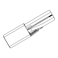
Details on using the provided bracket and screws for controller mounting.

Installation Steps and Warnings

Step-by-step instructions for securing the bracket, controller, and safety warnings.

Wiring Safety and Connection Precautions

Wire Connection Order and Grounding

Warnings about correct wire connection order and the importance of proper grounding.

General Wiring and Black Wire Cautions

Warnings about improper connections, controller damage, and black wire usage.

Controller Wiring and Circuit Protection

Wire Function and Connection Guide

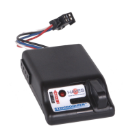
Describes the function, color, wire size, and connection for each controller wire.

Circuit Breaker Sizing Chart

Chart for selecting self-resetting circuit breaker sizes based on trailer configuration.

Special Vehicle Wiring Conditions

Factory Tow Package vs. No Tow Package

Guidance for vehicles with or without factory tow packages.

Ford Specific Wiring Instructions

Specific wiring instructions and warnings for certain Ford vehicle models.

Appendix: OEM Tow Vehicle Wiring Conversions

Vehicle Wiring Compatibility Chart

Table mapping OEM vehicle wires to controller functions for various manufacturers.

OPERATION MANUAL

READ AND SAVE THESE INSTRUCTIONS

Instructions to read and save before operation for future reference.

SAFETY INFORMATION

Defines warning, caution, and tip symbols used throughout the manual.

Automatic Operation and Controller Features

Automatic Operation Explained

How the controller senses deceleration and applies trailer brakes proportionally.

Digital Display and Controller Settings

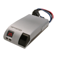
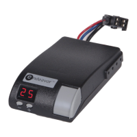
Description of display, features, options, selections, and settings.

Controller Configuration and Troubleshooting Codes

Display Mode and Minimum Power Settings

Explains display modes (P, E, C, PH, EH) and minimum power settings (5-25).

Maximum Power (Gain) and Error Codes

Explains gain settings (5-100) and lists potential trouble codes (SC, CL, OC, HF, bF).

Display Mode Operation and Warnings

Display Mode Functionality and Changes

Details display modes and provides step-by-step instructions to change them.

Operation and Adjustment Warnings

Warning about improper adjustment leading to brake issues or loss of control.

Minimum Power Adjustment Procedures

Minimum Power Setting Cautions

Cautions regarding minimum power settings and vehicle at rest behavior.

Manual and Automatic Minimum Power Adjustment

Step-by-step instructions to adjust the minimum power setting for manual and auto modes.

Maximum Power and Manual Lever Operation

Changing Maximum Power (Automatic Only)

Instructions to adjust the maximum power setting for automatic braking.

Manual Slide Lever Function and Safety

Explains the manual slide lever operation, its independent circuit, and a safety warning.

Road Test and Performance Adjustment

Verifying Wiring and Road Testing

Steps to verify wiring and conduct road tests for optimal controller setup.

Minimum Power Guidelines by Trailer Weight

Guidelines for setting minimum power based on loaded trailer weight.

Brake Controller Power Adjustments

Power Adjustment Methods Overview

Outlines Maximum Power Adjustment and Minimum Power Adjustment as two methods.

Maximum and Minimum Power Adjustment Details

Details on adjusting maximum and minimum power for optimal performance.

Operation Cautions

Cautions regarding minimum power settings and vehicle at rest behavior.

Display Troubleshooting - Error Codes

Short Circuit (SC) and Current Limit (CL) Displays

Explains SC and CL display codes indicating shorts, overloads, or wiring issues.

Troubleshooting Display Codes

Open Circuit (OC) and Hazard Flash (HF) Displays

Explains OC and HF display codes for no connection, E/H brakes, or brake light cycling.

Blue Wire Fault (bF) Display and Tips

Explains bF code for voltage on blue wire and provides general troubleshooting tips.

Comprehensive Troubleshooting Guide

Trailer Brakes Lock Up Issues

Lists possible causes and remedies for trailer brake lock up.

Low Output / Weak Brakes

Lists possible causes and remedies for low output or weak trailer brakes.

No Trailer Brake Output

Lists possible causes and remedies for no trailer brake output in various modes.

Intermittent or Surging Brakes

Lists possible causes and remedies for intermittent or surging trailer brakes.

Specific Troubleshooting Scenarios

SC, CL, bF, and OC Error Code Resolution

Lists possible causes and remedies for SC, CL, bF, and OC error codes.

Related product manuals