10 With the cam spindle removed, the
centrifugal advance weights can now be lifted
out.
11 To remove the vacuum unit, prise off the
small circlip located behind the knurled
adjustment wheel. Now unscrew the
adjustment wheel until the vacuum unit is
released and then withdraw the vacuum unit
from the distributor body. Note: A vacuum
unit is not fitted to the 23D4 type.
12 As the unit is withdrawn, retrieve the
adjustment wheel together with the tension
spring and spring plate. The spring plate is
responsible for the clicks when the
adjustment wheel is turned. This spring plate
together with the circlip are small and easily
lost so put them in a safe place.
13 It is only necessary to remove the
distributor driveshaft if it is thought to be
excessively worn. With a thin punch, drive out
the retaining pin from the driving dog on the
bottom end of the distributor driveshaft. The
shaft can then be removed.
Lucas 45D4 and 59D4
14 Remove the distributor from the car as
described in Section 8.
15 Withdraw the rotor arm from the
distributor spindle and then remove the
contact breaker points as described in
Section 6.
16 Push the low tension lead and grommet
through into the inside of the distributor body
(see illustration). Undo and remove the
single retaining screw and lift off the
condenser and low tension lead assembly.
Note that the condenser securing screw also
retains the baseplate earth lead.
17 Undo and remove the two vacuum unit
securing screws, tilt the vacuum unit to
disengage the pullrod from the baseplate peg,
and withdraw the unit.
18 Undo and remove the two screws
securing the baseplate and the earth lead to
the distributor body. Lift off the earth lead,
lever the slotted segment of the baseplate out
of its retaining groove and withdraw the
baseplate.
19 The distributor driveshaft should only be
removed if it is thought to be worn. After
removal it cannot be further dismantled, and if
necessary must be renewed as an assembly,
complete with centrifugal advance weights
and springs.
20 To remove the driveshaft, drift out the
retaining pin from the driving dog using a thin
punch. Remove the driving dog and
thrustwasher and then lift out the driveshaft
assembly.
Lucas 65DM4
21 Remove the distributor from the car as
described in Section 8.
22 Pull off the rotor arm (see illustration).
23 Remove the two screws and pull the
amplifier module from the connector, then
remove the gasket and pull off the connector.
24 Remove the screws, and separate the
upper housing from the lower housing.
25 Remove the clamp ring and pick-up
winding from the upper housing.
26 Remove the vacuum unit retaining screw,
then extract the circlip and thrustwasher,
withdraw the stator pack from the link arm, and
remove the vacuum unit. Recover the remaining
thrustwasher from the upper housing.
27 Further dismantling is not normally
necessary. However, the shaft assembly may
be removed from the lower housing by driving
the roll pin from the drive dog, after marking
the drive dog in relation to the shaft.
28 Clean and examine all the components,
and renew them as required.
Ducellier
29 Remove the distributor from the car as
described in Section 8.
30 Withdraw the rotor arm from the
distributor spindle and then remove the
contact breaker points as described in
Section 6.
31 Undo and remove the two screws that
secure the condenser, vacuum unit, and one
of the distributor cap retaining clips to the
distributor body (see illustration). Lift away
the condenser and clip.
32 Using a small screwdriver, extract the
circlip securing the serrated eccentric cam to
the D-post. Mark the position of the eccentric
cam in relation to the spring seat of the
vacuum unit operating link.
33 Detach the vacuum unit operating link and
the eccentric cam from the D-post and lift off
the vacuum unit. Store the eccentric cam and
the small circlip safely, as they are easily lost.
Ignition system 5B•13
5B
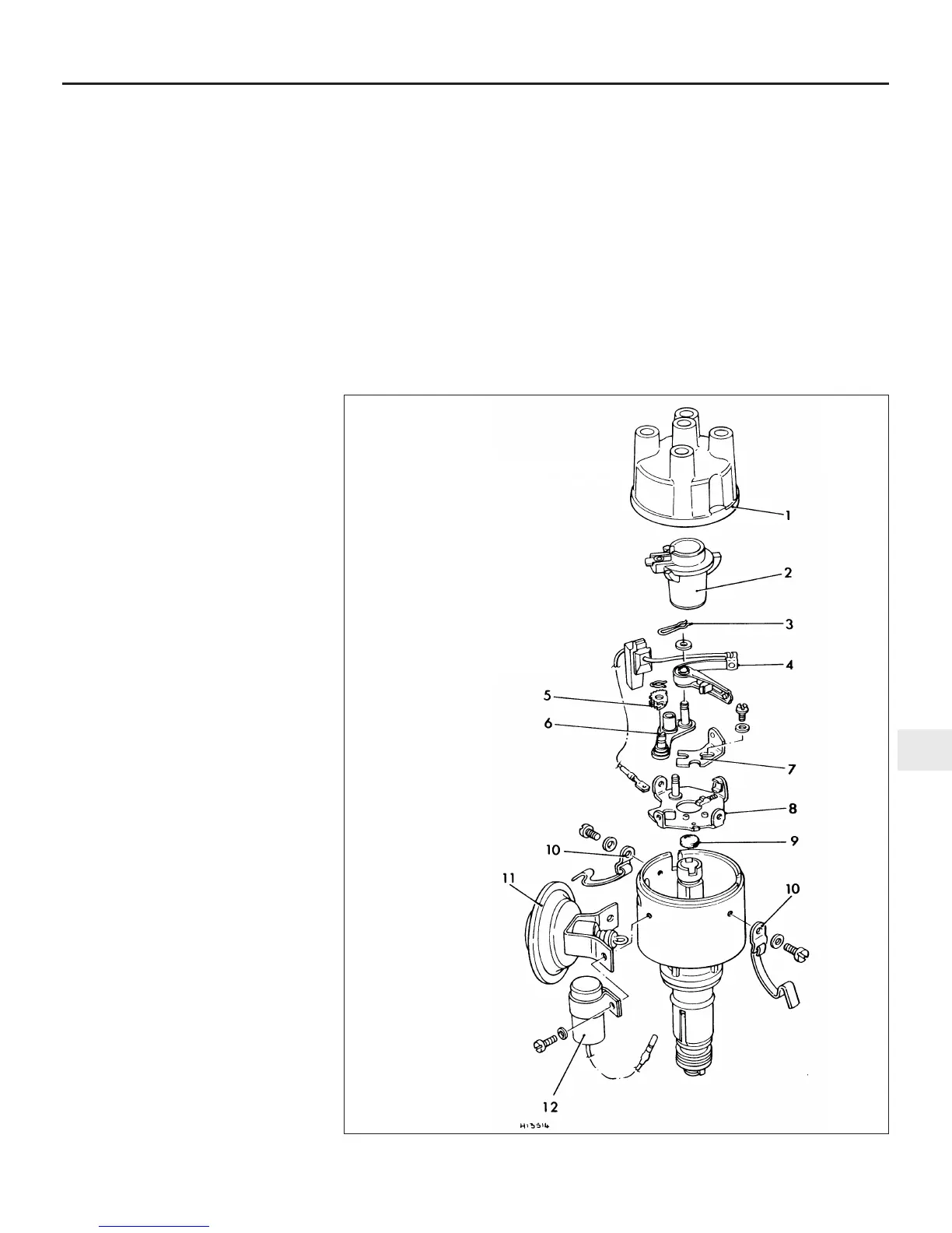
9.31 Exploded view of Ducellier distributor
1 Cap
2 Rotor
3 Rocker arm clip
4 Moving contact
assembly
5 Serrated cam
6 Eccentric D-post
7 Fixed contact
8 Baseplate
9 Felt pad
10 Cap retaining clips
11 Vacuum unit
12 Condenser
 Loading...