14 Using fingers only, place the secondary
cup seal in position on the piston with the lip
of the cup facing the opposite (drilled) end of
the piston.
15 Position the non-return valve over the
larger diameter of the spring and the spring
retainer over the smaller diameter, and place
this assembly into the cylinder bore, larger
diameter first.
16 Now insert the main cup seal into the
cylinder bore, lip end first followed by the
washer.
17 Insert the piston assembly into the
cylinder bore followed by the pushrod, dished
washer and circlip. Ensure that the circlip fully
enters its groove.
18 Lubricate a new dust cover with rubber
grease and stretch it over the pushrod and
into position on the end of the cylinder.
Refitting
19 Refitting is the reverse sequence to
removal. Bleed the complete hydraulic system
as described in Section 2 on completion.
13 Tandem master cylinder
(dual circuit system) -
identification and modifications
Identification
1 Four different versions of tandem brake
master cylinder have been fitted to Mini
models covered by this manual. The removal,
refitting and overhaul procedures for the four
versions are distinctly different and it is
important to correctly identify the unit being
worked on before proceeding.
2 For identification purposes only, the master
cylinders will be referred to in this Chapter as
types 1, 2, 3 or 4. Identification is as follows:
Type 1: Vertically mounted and
incorporating a circular plastic transparent
fluid reservoir with large flat filler cap (see
illustration). Separate pressure
differential warning actuator located on
engine compartment bulkhead.
Type 2: Vertically mounted and incorporating
a rectangular plastic transparent fluid
reservoir with small flat filler cap possibly
with brake fluid level warning indicator.
Upper and lower hydraulic pipe union nuts
of the same size. Pressure differential
warning actuator integral with master
cylinder, operating a brake failure warning
switch fitted to the side of the cylinder
body (see illustration).
Type 3: Vertically mounted and incorporating
a rectangular plastic transparent fluid
reservoir with brake fluid level warning
indicator in the filler cap. Upper hydraulic
pipe union nut larger than the lower nut. A
yellow plastic identification band should
also appear around the cylinder body (see
illustration). Fitted to models
manufactured from November 1985 to
1989 and as a retro-fit replacement for
type 2 units.
Type 4: Horizontally mounted on the front of
the vacuum servo unit. Fitted to models
manufactured from 1989 onwards (see
illustration).
Modifications
3 In November 1985, the type 3 tandem
master cylinder with a revised front/rear split
was introduced to replace the type 2. This
new cylinder has a stepped bore, and the
primary and secondary circuits have been
reversed.
4 Should a type 2 master cylinder require
renewal, a type 3 unit will be supplied by
Rover dealers.
5 To fit the type 3 cylinder to pre-November
1985 vehicles, two modified brake pipes will
be required and, on vehicles without a brake
fluid level warning indicator, a conversion
wiring loom will also be required. These
modified components should be available
from Rover dealers.
6 To fit a type 3 master cylinder to pre-
November 1985 vehicles, proceed as follows.
Braking system 9•11
9
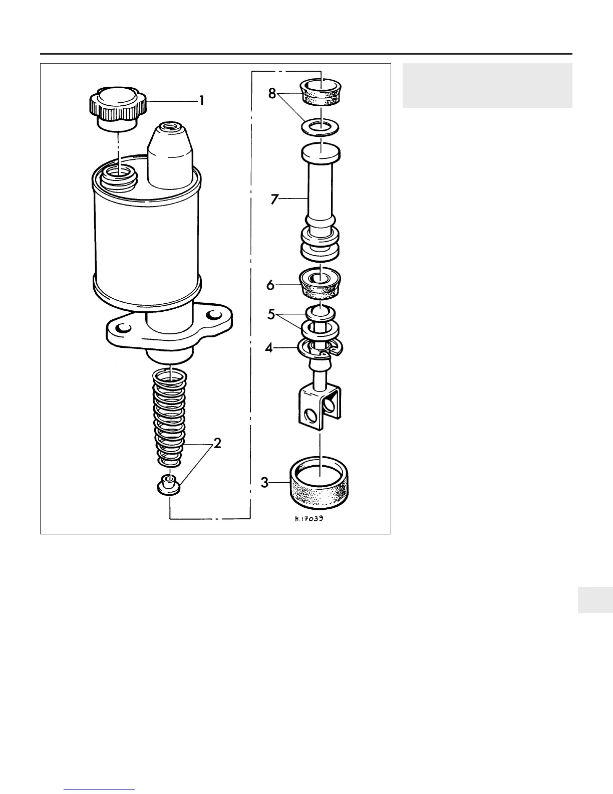
12.6 Exploded view of the single circuit master cylinder
1 Filler cap
2 Spring and spring retainer
3 Dust cover
4 Circlip
5 Pushrod and stop washer
6 Secondary cup seal
7 Piston
8 Piston washer and main cup seal
 Loading...