9•12 Braking system
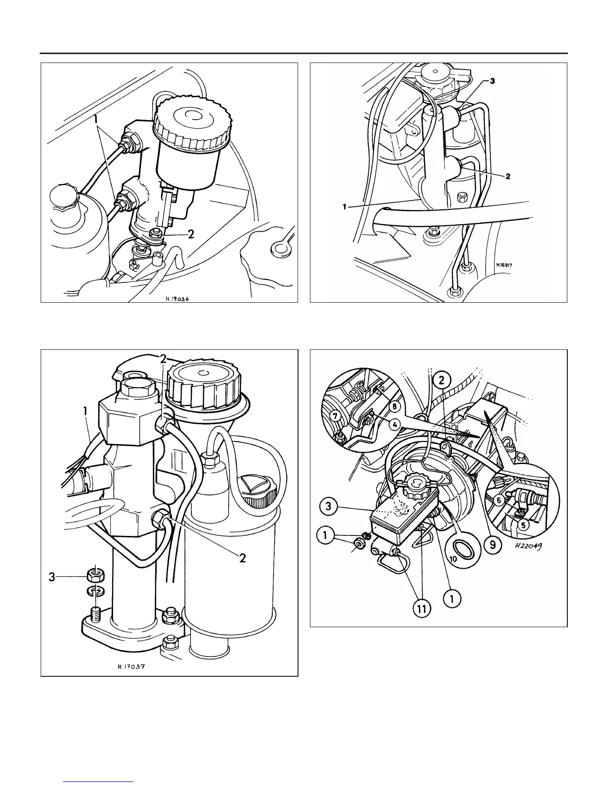
13.2a Identification and removal of the type 1 tandem
master cylinder
1 Hydraulic pipe unions 2 Retaining nuts
13.2b Identification and removal of the type 2 tandem
master cylinder
1 Electrical wiring to failure
switch
2 Hydraulic pipe unions
3 Retaining nuts
1 Yellow band 2 Larger pipe union 3 Smaller pipe union
13.2c Identification and removal of the type 3 tandem
master cylinder
13.2d Identification and removal of the type 4 tandem
master cylinder
1 Master cylinder mounting nuts
2 Vacuum hose retaining clip
3 One-way vacuum valve
4 Brake pedal clevis pin
5 Anti-run-on valve hoses
(where fitted)
6 Anti-run-on valve (where fitted)
7 Servo mounting bracket nuts
8 Servo pushrod clevis pin
9 Servo-to-mounting bracket
nuts
10 O-ring
11 Brake pipe union nuts
 Loading...