7 Remove the master cylinder, as described
in Section 15. Note: On vehicles equipped
with a fluid level indicator, disconnect the
wiring connectors from the switch on the
reservoir filler cap.
8 Remove the existing hydraulic pipes from
the pressure-reducing valve (which run to the
brake master cylinder).
9 Fit the new pipes to the pressure reducing
valve.
10 Fit the new brake master cylinder, which
is a reversal of removal, then connect the new
pipes to it.
11 To fit the wiring conversion loom, first cut
the connector from the end of the two black
and white wires removed from the brake
warning switch on the old cylinder (see
illustration).
12 Join the two wires together, fit a Lucar
connector, and connect it to one terminal of
the fluid level warning switch on the new
master cylinder.
13 Using black cable, make up an earth lead
with a Lucar connector at one end and an
eyelet at the other.
14 The earth lead should be 533.0 mm long,
and is connected to the other connector on
the fluid level warning switch, and routed
along the wiring loom in the engine bay to the
existing earth screw.
15 Fill and bleed the hydraulic system, as
described in Section 2, and check the
operation of both the brake warning light and
the low fluid level warning light.
14 Tandem master cylinder
(type 1) - removal, overhaul
and refitting
3
Note: Before starting work, refer to the
warning at the beginning of Section 2
concerning the dangers of hydraulic fluid.
Removal
1 Place a cloth around the master cylinder to
catch any spilled fluid then unscrew the
hydraulic pipe unions from the master cylinder
and carefully pull the pipes clear. Plug or tape
over the disconnected unions to prevent dirt
entry.
2 Undo and remove the two nuts and spring
washers securing the master cylinder to the
bulkhead. Lift off the master cylinder, leaving
the pushrod attached to the brake pedal.
Overhaul
3 Remove the filler cap from the master
cylinder, then drain and discard the hydraulic
fluid from the reservoir.
4 Mount the master cylinder In a vice with
protected jaws, so that the mouth of the
cylinder bore is uppermost.
5 Slide off the rubber boot, compress the
return spring and, using a small screwdriver,
remove the Spirolex ring from its groove in the
primary piston (see illustration). Take care
not to distort the coils of the ring or score the
bore of the cylinder.
6 Using a pair of circlip pliers, remove the
piston retaining circlip.
7 Carefully move the piston up and down in
the bore so as to free the nylon guide bearing
and cap seal. Lift away the guide bearing seal.
8 Lift away the plain washer.
9 Using a pair of circlip pliers, remove the
inner circlip.
10 The primary and secondary piston
assembly, complete with the stop washer,
may now be withdrawn from the cylinder bore.
Braking system 9•13
9
13.11 Braking system conversion wiring
loom details
A Loom B Earth screw
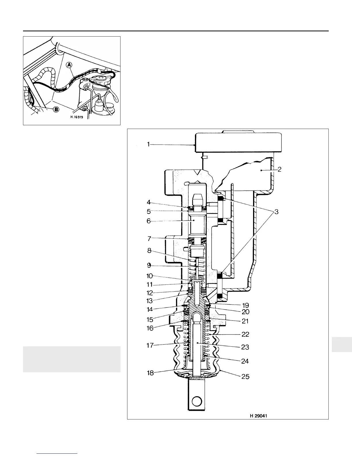
14.5 Cross-sectional view of
the type 1 tandem master
cylinder
1 Filler cap
2 Plastic reservoir
3 Reservoir seals
4 Main cap
5 Piston washer
6 Piston
7 Main cup
8 Spring
9 Piston link
10 Pin
11 Pin retainer
12 Main cup
13 Piston washer
14 Circlip
15 Cup
16 Circlip
17 Piston
18 Spring retainer
19 Stop washer
20 Washer
21 Bearing
22 Spring
23 Pushrod
24 Spirolex ring
25 Rubber boot
 Loading...