11 Lift away the stop washer.
12 Compress the spring that separates the
two pistons then, using a small diameter
parallel pin punch, drive out the roll pin that
retains the piston link.
13 Inspect and note the location of the
rubber cups (look for the moulded
indentations) then remove the cups and
washers from the pistons.
14 Undo and remove the four bolts that
secure the plastic reservoir to the body and lift
away the reservoir.
15 Recover the two reservoir sealing rings.
16 Unscrew and remove the hydraulic pipe
connection adapters, discard the copper
gaskets and recover the spring and trap
valves.
17 Wash all parts in clean hydraulic fluid or
methylated spirit and dry with a lint-free cloth.
18 Examine the bore of the cylinder carefully
for any signs of scores or ridges. If this is
found to be smooth all over, new seals can be
fitted. If, however, there is any doubt of the
condition of the bore, then a new cylinder
must be obtained and fitted. Never re-use old
seals as they will have deteriorated with age
even though this may not be evident during
visual inspection.
19 Reassembly of the master cylinder is the
reverse sequence to removal, but the
following additional points should be noted:
a) All components should be assembled wet
by dipping in clean brake fluid.
b) Locate the piston washer over the head of
the secondary piston, convex surface first,
then carefully ease the secondary cup
over the piston and seat it with its flat
surface against the washer.
c) Fit new copper gaskets to the connection
adapters.
Refitting
20 Refitting is the reverse sequence to
removal. On completion, bleed the complete
hydraulic system as described in Section 2.
15 Tandem master cylinder
(type 2) - removal, overhaul
and refitting
3
Note: Before starting work, refer to the
warning at the beginning of Section 2
concerning the dangers of hydraulic fluid.
Removal
1 From inside the car, release the heater air
inlet ducting from the side of the heater unit
and wheel arch. Remove the ducting from
under the parcel shelf.
2 Extract the split pin and withdraw the clevis
pin securing the master cylinder pushrod to
the brake pedal.
3 Working in the engine compartment,
disconnect the wiring connector from the
brake failure warning switch on the master
cylinder body.
4 Place a cloth around the master cylinder to
catch any spilled fluid then unscrew the
hydraulic pipe unions from the side of the
master cylinder body and carefully pull the
pipes clear. Plug or tape over the
disconnected unions to prevent dirt entry.
5 Unscrew the two nuts securing the master
cylinder to the bulkhead and lift the unit off.
Overhaul
6 Remove the filler cap from the master
cylinder, and drain and discard the hydraulic
fluid from the reservoir.
7 Mount the cylinder in a vice with protected
jaws, so that the reservoir is uppermost.
8 Unscrew the two reservoir retaining screws
and lift the reservoir off the master cylinder
body (see illustration). Carefully withdraw the
two reservoir sealing washers from the
outlets.
9 Push in the pushrod as far as possible, and
using pliers, extract the secondary piston stop
pin from its recess.
9•14 Braking system
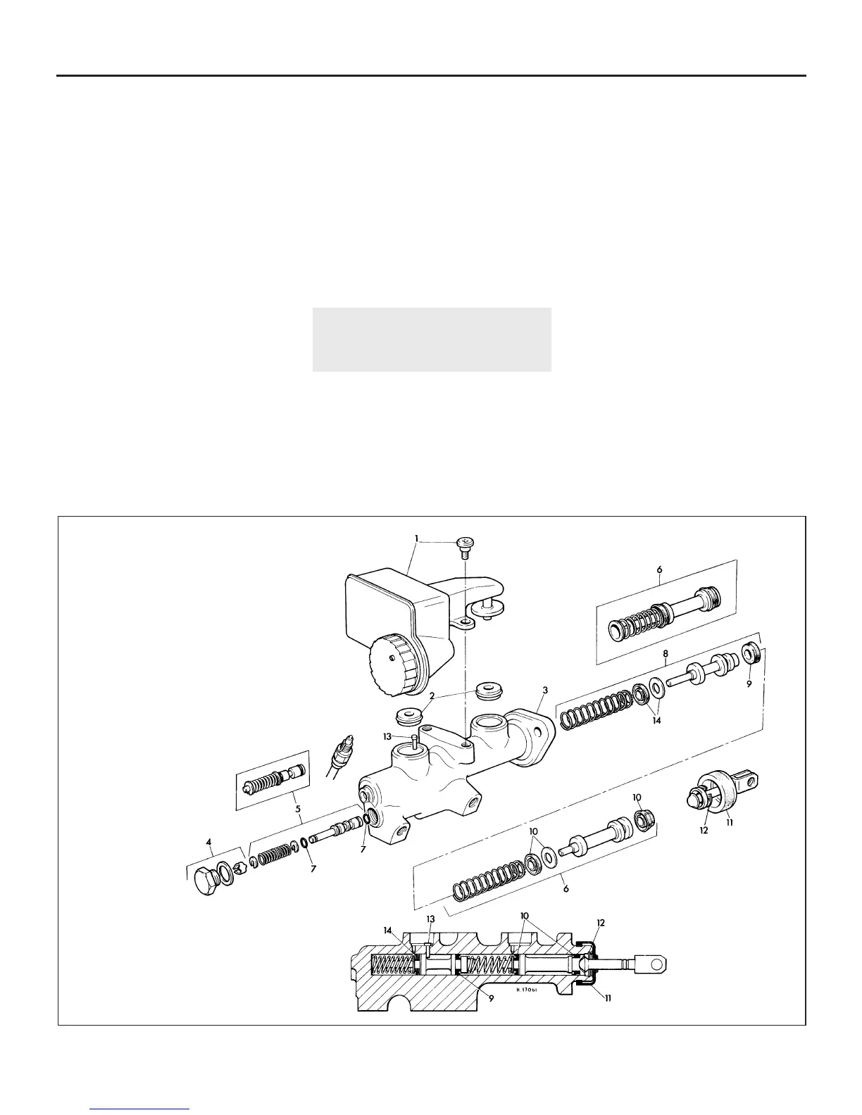
15.8 Exploded view of the type 2 tandem
master cylinder
1 Reservoir and retaining screw
2 Reservoir sealing washers
3 Master cylinder body
4 End plug assembly
5 Pressure differential piston
(insert shows alternative
assembly)
6 Primary piston and spring (inset
shows alternative assembly)
7 Piston rubber seals
8 Secondary piston and spring
9 Secondary piston seals
10 Primary piston
seals
11 Dust cover
12 Circlip
13 Stop pin
14 Secondary piston
seals
 Loading...