7 Front suspension tie-bar -
removal and refitting
2
Removal
1 Chock the rear wheels then jack up the
front of the car and support it on axle stands
(see “Jacking and vehicle support”). Remove
the front roadwheel.
2 Undo and remove the locknut securing the
front end of the tie-bar to the subframe (see
illustration). Now lift off the thrustwasher and
the rubber thrust bush.
3 Undo and remove the bolt, nut and spring
washer securing the other end of the tie-bar to
the lower suspension arm. Disengage the tie-
bar from the suspension arm and subframe,
then lift it off the car. Slide the remaining
rubber thrust bush off the tie-bar end.
4 Carefully inspect the tie-bar thrust bushes
for swelling, compression damage or
deterioration of the rubber and check the tie-
bar for straightness and elongation of the
mounting bolt holes. Also check the securing
bolt for wear of its shank. If any of the
components are defective a new tie-bar kit
should be obtained from your local dealer.
Refitting
5 Refitting is the reverse sequence to
removal.
8 Front upper suspension arm
- removal and refitting
4
Note: Before carrying out this operation on
cars fitted with Hydrolastic suspension, it will
be necessary to have the Hydrolastic system
depressurised by a Rover dealer. If working on
cars equipped with rubber cone suspension,
Rover special tool 18G574B will be required to
compress the rubber cone.
Removal
1 Chock the rear wheels then jack up the
front of the car and support it on axle stands
(see “Jacking and vehicle support”). Remove
the front roadwheel.
2 Undo and remove the nut and washer
securing the swivel hub balljoint to the upper
suspension arm. Release the taper of the
balljoint shank using a universal balljoint
separator, or the alternative method
described in Section 3, paragraph 5.
Models with Hydrolastic suspension
3 Undo and remove the single retaining
screw and lift out the upper suspension arm
rebound rubber.
4 Lift up the rubber dust cover around the
knuckle joint located on the top of the upper
suspension arm. Withdraw the ball end of the
knuckle joint from its seat in the upper arm
and then prise the shank of the knuckle joint
out of the displacer unit using a screwdriver.
The shank of the knuckle joint is a simple
push fit in the displacer unit; however,
corrosion may make it initially tight to remove.
Recover the spacer (where fitted) from the
shank.
Models with rubber cone suspension
5 Undo and remove the nut and flat washer
securing the shock absorber to the upper
suspension arm. Now move the shock
absorber sideways until it is clear of the
mounting stud.
6 Working in the engine compartment, undo
and remove the two bolts (or nuts) securing
the subframe tower to the bulkhead
crossmember. Lift off the locking plate and
then refit the bolts (or nuts). On later models
undo and remove the large hexagon-headed
plug that is used instead of the two bolts or
nuts (see illustration).
7 It is now necessary to compress the rubber
cone spring using service tool 18G574B as
follows. Position the body of the tool over the
two subframe tower retaining bolts (or nuts)
and turn the tool centre screw, nine complete
turns, to engage the threads in the rubber
cone. Now turn the ratchet handle of the tool
until it contacts the tool body. Hold the centre
screw and turn the ratchet handle clockwise
until all tension is removed from the strut
which interconnects the rubber cone and the
upper suspension arm (see illustration).
8 Undo and remove the single retaining
screw and lift out the upper suspension arm
rebound rubber.
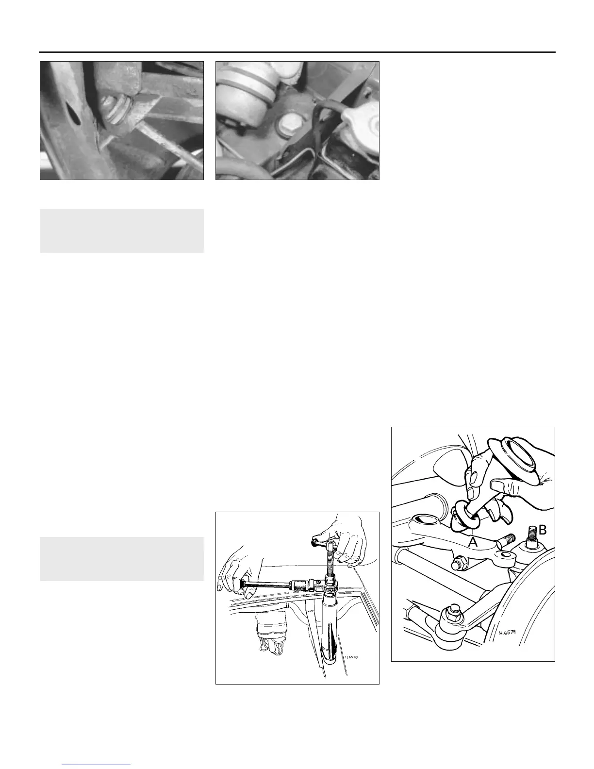
9 Lift up the rubber dust cover around the
knuckle joint located at the base of the spring
strut.
10 Withdraw the ball end of the knuckle joint
from its seat in the upper arm and then lift out
the spring strut assembly from the rubber
cone. If it is tight, prise it out using a
screwdriver (see illustration).
All models
11 Undo and remove the nut and spring
washer from each end of the upper arm pivot
shaft.
12 Undo and remove the two nuts, bolts and
spring washers securing the pivot shaft thrust
collar retaining plate, thrust collar and seal
and then withdraw the pivot shaft forward and
out of the upper suspension arm.
10•8 Suspension and steering
7.2 Tie-bar front mounting 8.6 Subframe tower mounting bolt fitted to
later models
8.7 Use of special tool to compress rubber
cone spring
8.10 Suspension strut removal - rubber
cone spring suspension
A Upper suspension arm
B Upper swivel hub balljoint
 Loading...