13 Now take out the rear thrust collar and
seal and then manipulate the upper arm out of
the subframe.
14 With the upper arm removed, inspect the
pivot shaft and the needle roller bearings for
wear, and if necessary renew them. The
needle roller bearings can be removed from
the upper arm by tapping them out of each
side using a long thin drift inserted through
the other side. Press in new bearings using a
vice, or drift them in using a tube of suitable
diameter or a shouldered mandrel. Ensure
that the marked ends of the bearings face
outwards.
15 Also carefully inspect the ball end of the
knuckle joint and its plastic cup seat in the
upper arm. If the ball end is corroded, worn or
pitted or if the plastic cup seat is cracked or
worn, renew the joint. The plastic cup seat
can be removed by prising out with a
screwdriver. The new knuckle joint will be
supplied fully assembled and the plastic cup
seat can be fitted to the arm with the joint in
this condition. The rubber dust cover and ball
end will then have to be removed to allow
refitment of the upper arm.
Refitting
16 Refitting is the reverse sequence to
removal bearing in mind the following points:
a) Lubricate all parts with general purpose
grease during reassembly.
b) If the original knuckle joint is being
refitted, pack the cup seat with
Dextragrease Super GP (or a suitable
alternative) available from Rover dealers.
c) Ensure that the dust cover is correctly
located over the knuckle joint cup, when
refitting, otherwise dirt and road grit will
enter the joint.
d) Ensure that all nuts and bolts are
tightened to the specified torque.
e) On models with Hydrolastic suspension,
do not drive the car (except to your
nearest Rover dealer) until the system has
been repressurised.
9 Front suspension rubber
cone spring - removal and
refitting
4
Removal
1 Remove the front upper suspension arm as
described in Section 8.
2 The service tool (18G574B) used to
compress the rubber cone must now be
released by turning the ratchet anti-clockwise
until all tension in the rubber cone is released.
3 Unscrew the service tool and withdraw the
rubber cone from its location in the subframe.
Refitting
4 Refitting is the reverse sequence to
removal.
10 Front suspension
Hydrolastic displacer unit -
removal and refitting
4
Removal
1 Remove the front upper suspension arm as
described in Section 8.
2 Using two large spanners, undo and
remove the displacer hose from the transfer
pipe union on the engine compartment
bulkhead.
3 Push the displacer unit upward, undo and
remove the two screws securing the displacer
retaining bracket to the subframe tower.
4 Rotate the displacer anti-clockwise and
withdraw it from its location on the subframe.
Refitting
5 Refitting is the reverse sequence to
removal. When installing the displacer, rotate
it clockwise to engage the registers on the
locating plate.
11 Front shock absorber (models
with rubber cone suspension)
- removal and refitting
2
Removal
1 Chock the rear wheels then jack up the
front of the car and support it on axle stands
(see “Jacking and vehicle support”). Remove
the front roadwheel.
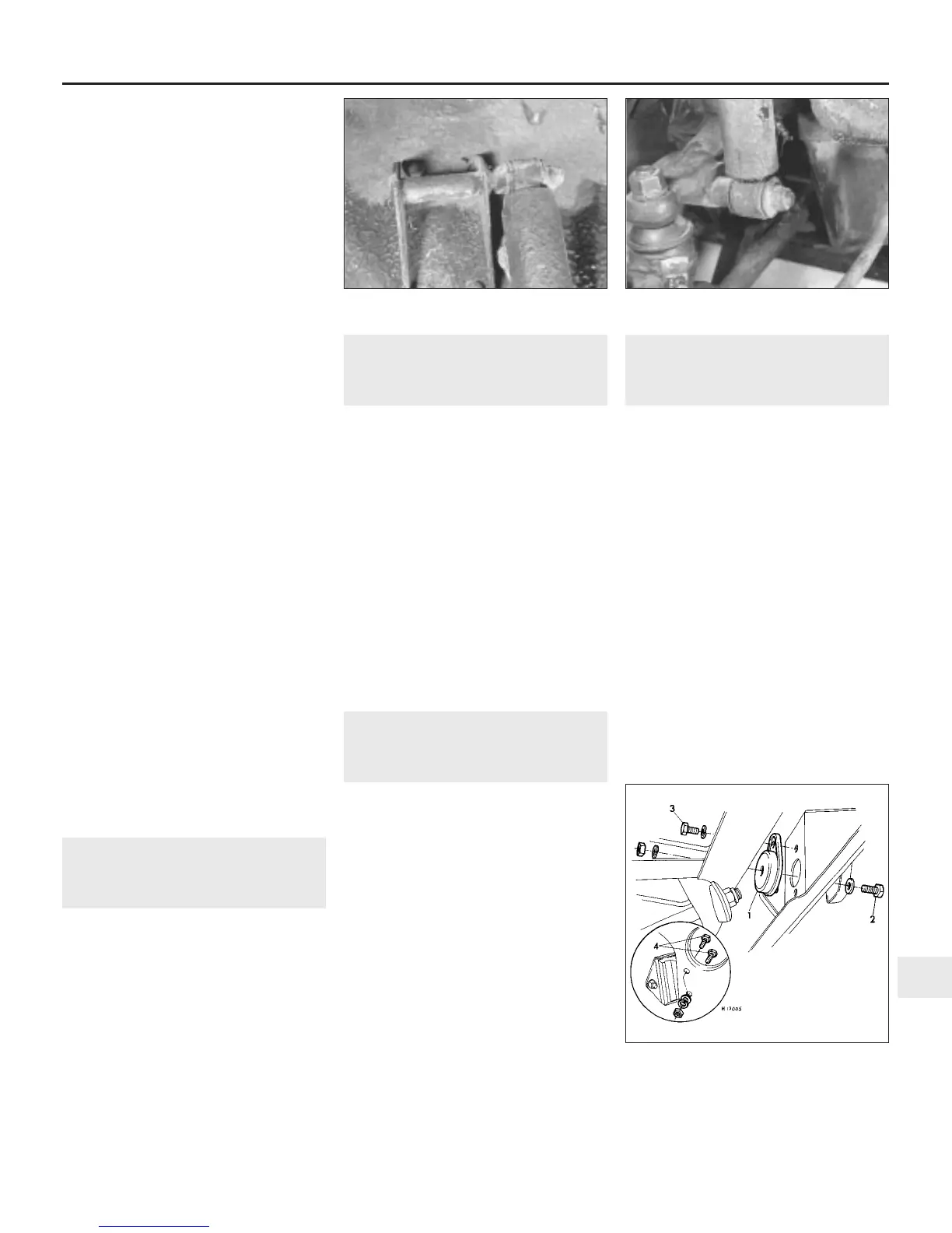
2 Undo and remove the shock absorber
upper and lower retaining nut and washers
and lift off the shock absorber (see
illustrations).
3 Examine the shock absorber for leaks or
damage of the outer casing. Hold the shock
absorber upright and fully compress and extend
it six times. Now slowly extend and compress it
again. If “dead” areas are apparent, if there is
free travel when changing direction, or if the unit
is damaged or leaking, it must be renewed.
Refitting
4 Refitting is the reverse sequence to removal.
Hold the shock absorber in an upright position
and fully compress and extend it six times to
expel any air before fitting.
12 Front subframe mountings -
renewal
3
Note: The following information is applicable
to later models equipped with bonded rubber
mountings between the front subframe and
vehicle underbody. The mountings can be
renewed with the subframe in position as
follows.
Front mountings
1 Chock the rear wheels then jack up the
front of the car and support it on axle stands
(see “Jacking and vehicle support”).
2 Support the subframe with a jack on the
side to be released.
3 Undo and remove the nut and bolt securing
the mounting to the subframe and the nut and
bolt securing the mounting to the body (see
illustration).
4 Undo and remove the two nuts and bolts
securing the subframe to the rear mounting.
5 Lower the jack slightly, lever the subframe
rearwards, and extract the front mounting.
Collect any shims that may be fitted between
the mounting and the subframe.
Suspension and steering 10•9
10
11.2a Shock absorber upper . . . 11.2b . . . and lower mounting
12.3 Front subframe mountings
1 Front mounting
2 Mounting-to-subframe retaining bolt
3 Mounting-to-body retaining bolt
4 Rear mounting-to-subframe retaining bolts
 Loading...