Refitting
7 Refitting is the reverse sequence to
removal, bearing in mind the following points:
a) Ensure that the small link rod on the lock
assembly is engaged with the operating
link of the exterior door handle.
b) If problems are experienced with the
operation of the lock, it is likely that the
inner remote control handle assembly is
incorrectly positioned. If the door fails to
lock, loosen the three retaining screws,
and move the remote control handle
assembly forwards to correct the
operation. If the door fails to unlock, move
the assembly rearwards.
Van and Pick-up models
Removal
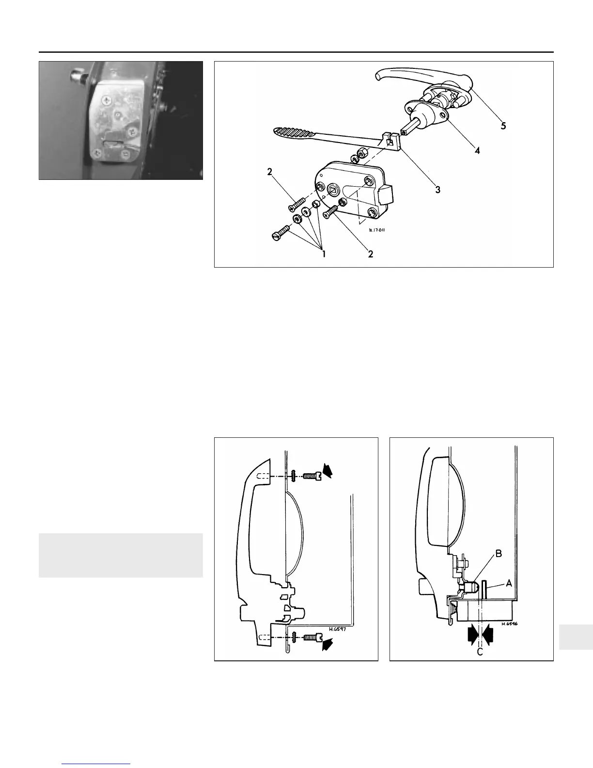
8 Undo and remove the three screws that
secure the lock body to the inner door panel
(see illustration).
9 Undo and remove the screw located at the
end of the locking handle spindle.
10 Slacken the inner handle clamp screw
(where fitted) and slide out the outer handle
and escutcheon. Now lift off the lock body.
Refitting
11 Refitting is the reverse sequence to
removal.
11 Front door exterior handle
(Saloon and Estate models) -
removal and refitting
1
Removal
1 Refer to Section 6 and remove the door
interior trim panel.
2 Undo and remove the screws securing the
interior lock control to the inner door panel.
3 Undo and remove the screws securing the
door lock assembly to the side of the door,
and move the lock up at the bottom and away
from the door.
4 Undo and remove the screws securing the
exterior handle to the door and lift the handle
off (see illustration).
5 With the handle removed, the lock barrel
and push button can be withdrawn as follows.
6 Prise off the retaining clip securing the lock
barrel to the handle.
7 Insert the key into the lock and withdraw
the lock barrel.
8 Undo and remove the screw securing the
retaining plate to the exterior handle.
9 Lift off the retaining plate, operating link,
washer, and spring. Now withdraw the push
button.
Refitting
10 Refitting is the reverse sequence to
removal. On the earlier type door handle the
push button plunger incorporates an
adjustable nylon cap over the plunger. The
adjustment of this cap is set during
manufacture, but if necessary it can be
screwed in or out slightly to give 1.0 to 1.5
mm of free play before contacting the door
lock release lever (see illustration).
Bodywork and fittings 11•7
11
10.4 . . . and the door lock retaining
screws
11.4 Exterior door handle securing screws
(arrowed) - Saloon and Estate models
11.10 Door handle push button plunger
adjustment
A Lock release
lever
B Plunger cap
C = 1.0 to 1.5 mm
10.8 Exploded view of the door lock and handle assembly fitted to Van and
Pick-up models
1 Lock handle spindle fixings
2 Lock body retaining screws
3 Interior handle
4 Seal
5 Exterior handle
 Loading...