seals in unmodified heads. Consult a Rover
dealer for further details of this modification.
20 If the valves are in satisfactory condition,
they should be ground (lapped) into their
respective seats, to ensure a smooth, gas-
tight seal. If the seat is only lightly pitted, or if
it has been re-cut, fine grinding compound
only should be used to produce the required
finish. Coarse valve-grinding compound
should not be used, unless a seat is badly
burned or deeply pitted. If this is the case, the
cylinder head and valves should be inspected
by an expert, to decide whether seat re-
cutting, or even the renewal of the valve or
seat insert (where possible) is required.
21 Valve grinding is carried out as follows.
Place the cylinder head upside-down on a
bench.
22 Smear a trace of (the appropriate grade
of) valve-grinding compound on the seat face,
and press a suction grinding tool onto the
valve head. With a semi-rotary action, grind
the valve head to its seat, lifting the valve
occasionally to redistribute the grinding
compound. A light spring placed under the
valve head will greatly ease this operation.
23 If coarse grinding compound is being
used, work only until a dull, matt even surface
is produced on both the valve seat and the
valve, then wipe off the used compound, and
repeat the process with fine compound. When
a smooth unbroken ring of light grey matt
finish is produced on both the valve and seat,
the grinding operation is complete. Do not
grind-in the valves any further than absolutely
necessary, or the seat will be prematurely
sunk into the cylinder head.
24 When all the valves have been ground-in,
carefully wash off all traces of grinding
compound using paraffin or a suitable solvent,
before reassembling the cylinder head.
Valve components
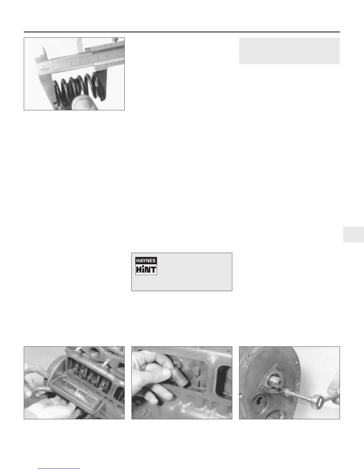
25 Examine the valve springs for signs of
damage and discoloration. Measure their free
length and compare the dimension with the
figures given in the Specifications (see
illustration).
26 Stand each spring on a flat surface, and
check it for squareness. If any of the springs
are damaged, distorted or shorter than the
specified length, obtain a complete new set of
springs. It is normal to renew the valve springs
as a matter of course if a major overhaul is
being carried out.
27 Renew the valve stem oil seals regardless
of their apparent condition.
Reassembly
28 Lubricate the stems of the valves, and
insert the valves into their original locations. If
new valves are being fitted, insert them into
the locations to which they have been ground.
29 As each valve is inserted, slip the oil seal
into place just under the bottom of the collet
groove. A much larger oil seal is used on the
1275 cc engines. This should be fitted over
the top of the valve guide.
30 Refit the valve spring(s), valve guide shield
(early models) and the spring retainer.
31 Compress the valve spring, and locate the
split collets in the recess in the valve stem.
Release the compressor, then repeat the
procedure on the remaining valves.
32 With all the valves installed, place the
cylinder head face down on blocks on the
bench and, using a hammer and interposed
block of wood, tap the end of each valve stem
to settle the components.
33 The cylinder head can then be refitted as
described in Part A of this Chapter.
9 Camshaft and tappets -
removal, inspection and
refitting
3
Note: The camshaft can only be removed with
the engine out of the car and on the bench.
With the cylinder head, timing cover, gears
and chain, fuel pump and distributor drivegear
removed, proceed as follows.
Removal
1 On 848, 998 and 1098 cc engines, undo
and remove the bolt securing each tappet
block side cover to the rear of the cylinder
block and lift off the covers (see illustration).
2 Lift out each tappet from its location in the
cylinder block and ensure that they are kept in
the correct sequence in which they were
removed (see illustration). Note: On 1275 cc
engines, tappet block side covers are not
fitted and the tappets can only be removed
after removing the camshaft.
3 Undo and remove the three bolts and
spring washers securing the camshaft
locating plate to the cylinder block. Lift off the
plate (see illustration).
4 On 848, 998 and 1098 cc engines, carefully
withdraw the camshaft from the cylinder
block, taking care not to damage the
camshaft bearings with the cam lobes as it is
withdrawn.
5 On 1275 cc engines position the engine on
its side to prevent the tappets falling out, then
slide out the camshaft. Recover the oil pump
drive coupling from the end of the camshaft
after removal. Now lift out each tappet, from
inside the crankcase, keeping them in the
correct sequence in which they were
removed.
6 On all engines, if further dismantling is to be
carried out, undo the bolts still remaining and
lift off the engine front plate. Recover the
gasket and clean the mating surfaces of the
front plate and cylinder block.
Inspection
Camshaft and camshaft bearings
7 Carefully examine the camshaft bearings
for wear. Note: On 848 cc engines, only the
front camshaft bearing is renewable. If the
bearings are obviously worn or pitted or the
Engine removal and overhaul procedures 2B•13
2B
8.25 Measuring valve spring free length
9.1 Removing the tappet side covers 9.2 Removing the cam followers 9.3 Undo the camshaft locating plate bolts
and lift off the plate
Use a little dab of grease to
hold the collets in position
on the valve stem while the
spring compressor is
released.
 Loading...