11 Piston/connecting rod -
removal, inspection,
separation and reconnection
3
Removal
1 With the engine separated from the
transmission and the cylinder head removed,
the piston/connecting rod assemblies can be
removed as follows.
2 Knock back the locking tabs on the big-end
bearing cap retaining bolts, using a small
chisel and remove the bolts and locking tabs.
The 1275 cc engine does not have locking
tabs and the big-end caps are retained by
bolts and special multi-sided nuts.
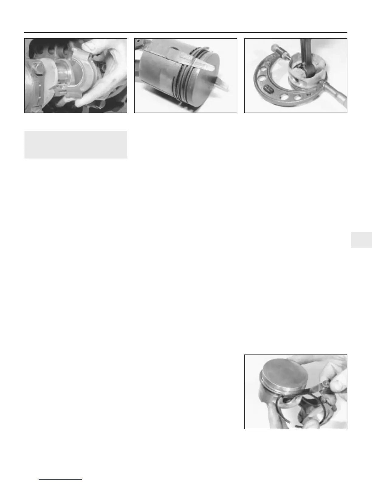
3 Remove the big-end caps one at a time,
taking care to keep them in the right order and
the correct way round (see illustration). Also
ensure that the shell bearings are kept with
their correct connecting rods and caps unless
they are to be renewed. Normally, the numbers
1 to 4 are stamped on adjacent sides of the
big-end caps and connecting rods, indicating
which cap fits on which rod and which way
round that cap fits. If no numbers or lines can
be found then, with a sharp screwdriver,
scratch mating marks across the joint from the
rod to the cap. One line for connecting rod No
1, two for connecting rod No 2, and so on. This
will ensure that there is no confusion later, as it
is essential that the caps go back in the
correct position on the connecting rods from
which they were removed.
4 If the big-end caps are difficult to remove
they may be gently tapped with a soft mallet.
5 To remove the shell bearings, press the
bearing opposite the groove in both the
connecting rod and the connecting rod caps,
and the bearings will slide out easily.
6 Withdraw the pistons and connecting rods
upwards and ensure that they are kept in the
correct order for refitting in the same bore.
Refit the connecting rod caps and bearings to
the rods if the bearings do not require
renewal, to minimise the risk of getting the
caps and rods muddled.
Inspection
7 Before the inspection process can begin,
the piston/connecting rod assemblies must
be cleaned, and the original piston rings
removed from the pistons.
8 Carefully expand the old rings over the top
of the pistons. The use of two or three old
feeler blades will be helpful in preventing the
rings dropping into empty grooves (see
illustration). Be careful not to scratch the
piston with the ends of the ring. The rings are
brittle, and will snap if they are spread too far.
They are also very sharp - protect your hands
and fingers. Always remove the rings from the
top of the piston. Keep each set of rings with
its piston if the old rings are to be re-used.
9 Scrape away all traces of carbon from the
top of the piston. A hand-held wire brush (or a
piece of fine emery cloth) can be used, once
the majority of the deposits have been
scraped away.
10 Remove the carbon from the ring grooves
in the piston, using an old ring. Break the ring
in half to do this (be careful not to cut your
fingers - piston rings are sharp). Be careful to
remove only the carbon deposits - do not
remove any metal, and do not nick or scratch
the sides of the ring grooves.
11 Once the deposits have been removed,
clean the piston/connecting rod assembly
with paraffin or a suitable solvent, and dry
thoroughly. Make sure that the oil return holes
in the ring grooves are clear.
12 If the pistons and cylinder bores are not
damaged or worn excessively, the original
pistons can be refitted. Normal piston wear
shows up as even vertical wear on the piston
thrust surfaces, and slight looseness of the
top ring in its groove. New piston rings should
always be used when the engine is
reassembled.
13 Carefully inspect each piston for cracks
around the skirt, around the gudgeon pin
holes, and at the piston ring “lands” (between
the ring grooves).
14 Look for scoring and scuffing on the piston
skirt, holes in the piston crown, and burned
areas at the edge of the crown. If the skirt is
scored or scuffed, the engine may have been
suffering from overheating, and/or abnormal
combustion which caused excessively high
operating temperatures. The cooling and
lubrication systems should be checked
thoroughly. Scorch marks on the sides of the
pistons show that blow-by has occurred. A
hole in the piston crown, or burned areas at
the edge of the piston crown, indicates that
abnormal combustion (pre-ignition, knocking,
or detonation) has been occurring. If any of the
above problems exist, the causes must be
investigated and corrected, or the damage will
occur again. The causes may include incorrect
ignition timing, or a carburettor or fuel injection
system fault.
15 Corrosion of the piston, in the form of
pitting, indicates that coolant has been
leaking into the combustion chamber and/or
the crankcase. Again, the cause must be
corrected, or the problem may persist in the
rebuilt engine.
16 Using a micrometer, measure the
diameter of all four pistons at a point 10 mm
from the bottom of the skirt, at right angles to
the gudgeon pin axis (see illustration).
Record the measurements and use them to
check the piston-to-bore clearance when the
cylinder bores are measured later in this
Chapter.
17 Hold a new piston ring in the appropriate
groove and measure the ring-to-groove
clearance using a feeler blade (see
illustration). Note that the rings are of
different types, so use the correct ring for the
groove. Compare the measurements with
those listed in the Specifications; if the
clearances are outside the tolerance range,
then the pistons must be renewed.
18 When new pistons are to be fitted, take
great care to be sure to fit the exact size best
suited to the particular bore of your engine.
Rover go one stage further than merely
specifying one size piston for all standard
Engine removal and overhaul procedures 2B•15
2B
11.3 Removing a connecting rod big-end
cap
11.8 Using feeler blades to aid removal of
the piston rings
11.16 Measuring the piston diameter
11.17 Measuring the piston ring-to-groove
clearance
 Loading...