bores. Because of very slight differences in
cylinder machining during production, it is
necessary to select just the right piston for the
bore. A range of different sizes are available
either from the piston manufacturer or from a
Rover dealer.
19 Examination of the cylinder block face will
show, adjacent to each bore, a small
diamond-shaped box with a number stamped
in the metal. Careful examination of the piston
crown will show a matching diamond and
number (see illustration). These are the
standard piston sizes and will be the same for
all bores. If the standard pistons are to be
refitted or standard low compression pistons
changed to standard high compression
pistons, then it is essential that only pistons
with the same number in the diamond are
used. With oversize pistons fitted after a
rebore, the amount of oversize is stamped in
an ellipse on the piston crown.
20 Examine each connecting rod carefully for
signs of damage, such as cracks around the
big-end and small-end bearings. Check that
the rod is not visibly bent or distorted.
Damage is highly unlikely, unless the engine
has been seized or badly overheated. Detailed
checking of the connecting rod assembly can
only be carried out by a Rover dealer or
engine repair specialist with the necessary
equipment.
Separation
21 Three different methods of gudgeon pin
retention are employed, depending on the
type and cubic capacity of the engine.
22 On the 848 cc engines the gudgeon pin is
clamped firmly in place by a pinch-bolt
located in the end of the connecting rod (see
illustration). To remove the piston from the
connecting rod it is merely necessary to undo
and remove the pinch-bolt and slide out the
gudgeon pin. If it shows reluctance to move,
do not force it as this may damage the piston.
Immerse the piston in boiling water for a few
minutes; the expansion of the aluminium
should allow the pin to slide out easily.
23 On early 998 cc and all 1098 cc engines,
fully floating gudgeon pins are used, these
being retained in position by a circlip at each
end of the gudgeon pin bore in the piston. To
remove the gudgeon pin and piston, withdraw
the circlip from one end and push the pin out,
immersing it in boiling water if it appears
reluctant to move.
24 On later 998 cc and all 1275 cc engines
the gudgeon pin is firmly held in the small-end
of the connecting rod by an interference fit.
Removal of the gudgeon pin calls for the use
special tools and a good deal of experience to
use them correctly. Therefore, piston and/or
connecting rod renewal should be entrusted
to a Rover dealer or engine repair specialist,
who will have the necessary tooling to remove
and install the gudgeon pins.
25 On early 998 cc and all 1098 cc engines,
check the fit of the gudgeon pin in the
connecting rod bush and in the piston. If there
is perceptible play, a new bush or an oversize
gudgeon pin must be fitted. Consult a Rover
dealer or engine reconditioning specialist.
26 Examine all components and obtain any
new parts required. If new pistons are
purchased, they will be supplied complete
with gudgeon pins and, where applicable,
circlips. Circlips can also be purchased
separately.
Reconnection
27 If the original pistons are being used, then
they must be mated to the original connecting
rod with the original gudgeon pin. If new
pistons and gudgeon pins are being fitted, it
does not matter which connecting rod they
are used with.
28 The gudgeon pin may be a very tight fit in
the piston when cold (particularly on pistons
which have a small-end clamp bolt) but,
because aluminium has a greater coefficient
of expansion than steel, this fit will be much
easier if the piston is heated in boiling water.
29 Lay the correct piston adjacent to its
connecting rod and remember that the
original rod and piston must go back into the
original bore. If new pistons are being used, it
is only necessary to ensure that the right
connecting rod is placed in each bore.
Gudgeon pins retained by clamp bolts
30 Locate the small-end of the connecting
rod in the piston with the marking “FRONT”
on the piston crown towards the front of the
engine and the hole for the gudgeon pin bolt
in the connecting rod towards the camshaft.
31 Note the indentation in the centre of the
gudgeon pin, and insert the pin in the
connecting rod, so that the indentation lines
up with the clamp bolt hole in such a way that
the bolt will pass through without touching the
gudgeon pin.
32 For the gudgeon pin to fit correctly, it
should slide in three quarters of its travel quite
freely and for the remaining quarter have to be
tapped in with a plastic or wooden headed
hammer. If the piston is heated in water then
the pin will slide in the remaining quarter
easily.
33 Fit a new spring washer under the head of
the connecting rod bolt and secure it into
position to the specified torque. Repeat this
procedure for the remaining pistons and
connecting rods.
Fully floating gudgeon pins
34 Fit a gudgeon pin circlip in position at one
end of the gudgeon pin hole in the piston.
35 Locate the connecting rod in the piston
with the marking “FRONT” on the piston
crown towards the front of the engine, and the
connecting rod big-end caps towards the
camshaft side of the engine.
36 Slide the gudgeon pin in through the hole
in the piston and through the connecting rod
small-end until it rests against the previously
fitted circlip. Note that the pin should be a
push fit.
37 Fit the second circlip in position. Repeat
this procedure for the remaining pistons and
connecting rods.
Interference fit gudgeon pins
38 As stated previously, removal and refitting
of the gudgeon pin on these engines is a
delicate operation requiring the use of special
tools. This task must be entrusted to a Rover
dealer or engine repair specialist.
12 Crankshaft - removal and
inspection
3
Removal
1 With reference to Part A of this Chapter,
and earlier Sections of this Part as applicable,
carry out the following:
a) Separate the engine from the
transmission.
b) Remove the cylinder head.
c) Remove the piston/connecting rod
assemblies.
d) Remove the timing cover, chain, tensioner
and sprockets.
e) Remove the camshaft locating plate and
engine front plate.
Note: If no work is to be done on the pistons
and connecting rods, then removal of the
cylinder head and pistons will not be
necessary. Instead, after disconnecting the
connecting rods from the crankshaft, the
pistons need only be pushed far enough up
the bores so that they are positioned clear of
the crankpins.
2B•16 Engine removal and overhaul procedures
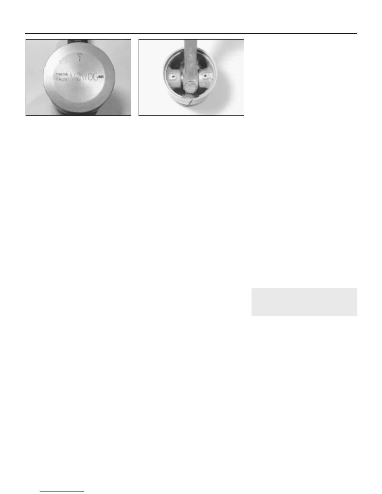
11.19 Identification markings on the
piston crown
11.22 Gudgeon pin clamped in place by a
pinch-bolt (848 cc)
 Loading...