1 Remove the radiator (Section 4).
2 Remove the fan belt as described in
Chapter 1, then undo and remove the two
nuts, bolts and washers securing the dynamo
or alternator to the mounting bracket and
water pump flange. Move the dynamo or
alternator away from the engine, pivoting it on
the adjusting arm bolt, and allow the unit to
rest against the body front panel.
3 Undo and remove the bolts securing the fan
and fan pulley to the water pump hub. Lift off
the fan and pulley, and where fitted recover
the spacer. As a guide to reassembly, make a
mark to indicate the outer face of the fan as it
is quite easy to refit this component the wrong
way round.
4 Slacken the hose clips and detach the
radiator bottom hose from the water pump
outlet and also from the heater take-off
connection, where applicable. Now slacken
the clip that secures the bypass hose to the
outlet on the top of the pump.
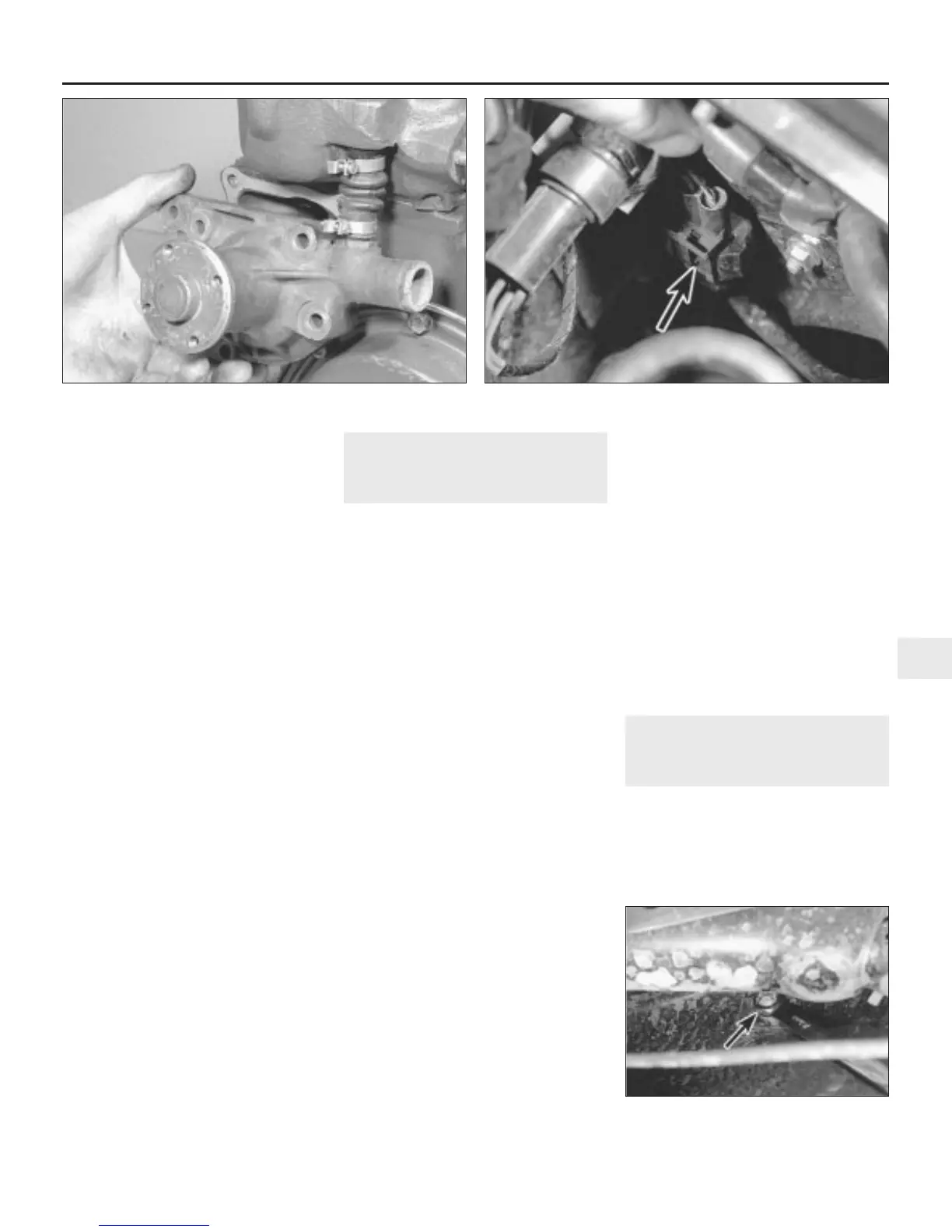
5 Undo and remove the four bolts securing
the water pump to the cylinder block. Lift off
the pump, and at the same time detach the
bypass hose. Recover the water pump gasket
(see illustration).
6 Before refitting the pump, clean off all
traces of old gasket from the water pump and
cylinder block mating faces, ensuring that the
faces are smooth, clean and dry.
Refitting
7 Refitting the water pump is the reverse
sequence to removal, bearing in mind the
following points:
a) Always use a new gasket, which should
be lightly smeared on both sides with
jointing compound.
b) The bypass hose should be renewed as a
matter of course, because these hoses
sometimes prove unreliable and are
extremely difficult to renew when the
water pump is installed.
c) Refit and adjust the fan belt as described
in Chapter 1.
d) Refit the radiator as described in Section 4.
7 Auxiliary cooling fan -
general information, removal
and refitting
2
General information
1 An auxiliary electric cooling fan is fitted to
all later 1275 cc engine models. It is located
beneath the left-hand front wheel arch, and
provides an additional source of cooling for
the radiator in conjunction with the belt-driven
fan on the water pump.
2 The auxiliary cooling fan is switched on and
off by a thermostatic switch. On carburettor
engine Cooper models, the switch is screwed
into the thermostat housing body on the
cylinder head, whereas on all other models it
is situated in the front bottom corner of the
radiator.
Removal - carburettor engine
Cooper models
3 Chock the rear wheels then jack up the
front of the car and support it on axle stands
(see “Jacking and vehicle support”). Remove
the left-hand front roadwheel.
4 Disconnect the air duct from the adapter
beneath the front left-hand headlight.
5 Trace the fan motor wiring back to its
connector, and disconnect it from the main
wiring harness.
6 Slacken and remove the four cooling fan
assembly shroud mounting nuts, and remove
the assembly from underneath the wheel arch.
Recover the mounting brackets, rubbers and
spacers.
Removal - all except carburettor
engine Cooper models
7 Remove the front grille as described in
Chapter 11.
8 Undo the three mounting bolts and remove
the radiator upper mounting bracket. Loosen
the lower radiator mounting bolt.
9 Disconnect the fan motor wiring connector,
which is situated by the side of the radiator
filler cap (see illustration), and release the
wiring grommet from the wing valance.
10 Slacken and remove the three (one lower
and two upper) mounting nuts securing the
fan shroud to the wing valance, then carefully
withdraw the cooling fan assembly from
underneath the wheel arch (see illustration).
Recover any relevant mounting rubbers and
spacers.
Refitting - all models
11 Refitting is the reverse sequence to
removal, noting that the mounting rubbers
should be renewed if they show any signs of
wear or deterioration. Ensure that all disturbed
nuts and bolts are securely tightened.
8 Auxiliary cooling fan
thermostatic switch -
removal, testing and refitting
2
Note: Refer to the warnings given in Section 1
of this Chapter before proceeding.
Removal
1 When the engine and radiator are cold,
either drain the cooling system as described
Cooling, heating and ventilation systems 3•5
3
7.10 Removing the lower fan mounting nut
(arrowed) - fuel injection models
6.5 Removing the water pump (shown with engine removed) 7.9 Auxiliary fan motor wiring connector (arrowed) -
fuel injection models
 Loading...