in Chapter 1, or carefully unscrew the radiator
filler cap to release any remaining pressure,
and have ready a suitable plug that can be
used temporarily to stop the escape of
coolant while the switch is removed. If the
latter method is used, take care not to
damage the threads, and do not use anything
which will leave foreign matter inside the
cooling system.
2 On carburettor engine Cooper models,
disconnect the wiring connectors, then
unscrew the switch from the thermostat
housing.
3 On all other models, if necessary remove the
front grille as described in Chapter 11 to
improve access to the switch. Disconnect the
two wiring connectors, then rotate the locking
ring anti-clockwise to release it; withdraw the
switch and rubber sealing ring from the bottom
corner of the radiator (see illustration).
Examine the sealing ring for signs of damage
or deterioration, and renew if necessary.
Testing
4 To carry out a thorough test of the switch,
use two spare wires to connect it either to a
multimeter (set to the resistance function) or to
a battery-and-bulb test circuit. Suspend the
switch in a pan of water which is being heated.
Measure the temperature of the water with a
thermometer. Do not let either the switch or
the thermometer touch the pan itself.
5 The switch contacts should close to the
“on” position (ie, continuity should exist) when
the water reaches the specified switch-on
temperature given in the Specifications at the
start of this Chapter. Stop heating the water,
and allow it to cool down; the switch
contacts should open at the specified
switch-off temperature.
6 If the switch performance is significantly
different from that specified, or if it does not
work at all, it must be renewed.
Refitting
7 On carburettor engine Cooper models,
ensure that the threads of the switch are
clean, then apply a smear of suitable sealant
to them. Refit the switch to the thermostat
housing, tightening it to the specified torque,
and reconnect the wiring connectors.
8 On all other models, fit the sealing ring to
the switch, then refit the switch to the radiator
and secure it in position with the locking ring.
Reconnect the wiring connectors, and refit the
front grille (where removed).
9 On completion, either top-up or refill the
cooling system as described in “Weekly
Checks” or Chapter 1.
9 Heater water valve control
cable - removal and refitting
2
Removal
1 Disconnect the battery negative lead.
2 On pre-1989 models, slacken the inner
cable trunnion screw and the outer cable
clamp screw at the heater water valve on the
cylinder head. Release the cable from the
valve. On 1989 models onward, release the
outer cable retaining clip from the heater
water valve on the engine compartment
bulkhead. Disconnect the inner cable from the
valve lever. Release the cable from its support
clips.
3 From inside the car, undo and remove the
screws, securing the centre console (where
fitted). This will enable the console to be
moved slightly as necessary to provide
access to the control cable and heater.
4 Slacken the nut securing the rear of the
heater unit to its mounting bracket.
5 Undo and remove the two screws securing
the heater unit to the parcel shelf and lower
the heater.
6 Detach the heater switch wire from the rear
of the switch.
7 Undo and remove the two nuts securing the
switch panel to the bracket under the parcel
shelf.
8 Pull the switch panel forward slightly, undo
the control cable retaining nut, and pull the
complete cable through into the car. Recover
the nut and washer from the end of the cable
as it is pulled through.
Refitting
9 Refitting the cable is the reverse sequence
to removal.
10 Heater water valve - removal
and refitting
2
Note: Refer to the warnings given in Section 1
of this Chapter before proceeding.
Removal
Pre-1989 models
1 Drain the cooling system as described in
Chapter 1.
2 Slacken the clip and disconnect the heater
hose from the valve.
3 Slacken the inner cable trunnion screw and
the outer cable clamp screw at the water
valve, and release the control cable from the
valve.
4 Undo the two nuts and remove the valve
from the cylinder head studs.
1989 models onwards
5 Drain the cooling system as described in
Chapter 1.
6 Slacken the clips and disconnect the heater
hoses from both sides of the valve (see
illustration).
7 Release the outer cable retaining clip and
disconnect the control cable from the valve
lever.
8 Remove the valve assembly from the
bulkhead.
Refitting
9 Refitting is the reverse sequence to
removal, but check that the valve can be
moved through its full range of travel. If
necessary, adjust by repositioning the control
outer cable in its clamp or retaining clip.
3•6 Cooling, heating and ventilation systems
8.3 Auxiliary cooling fan switch location
(arrowed) - fuel injection models
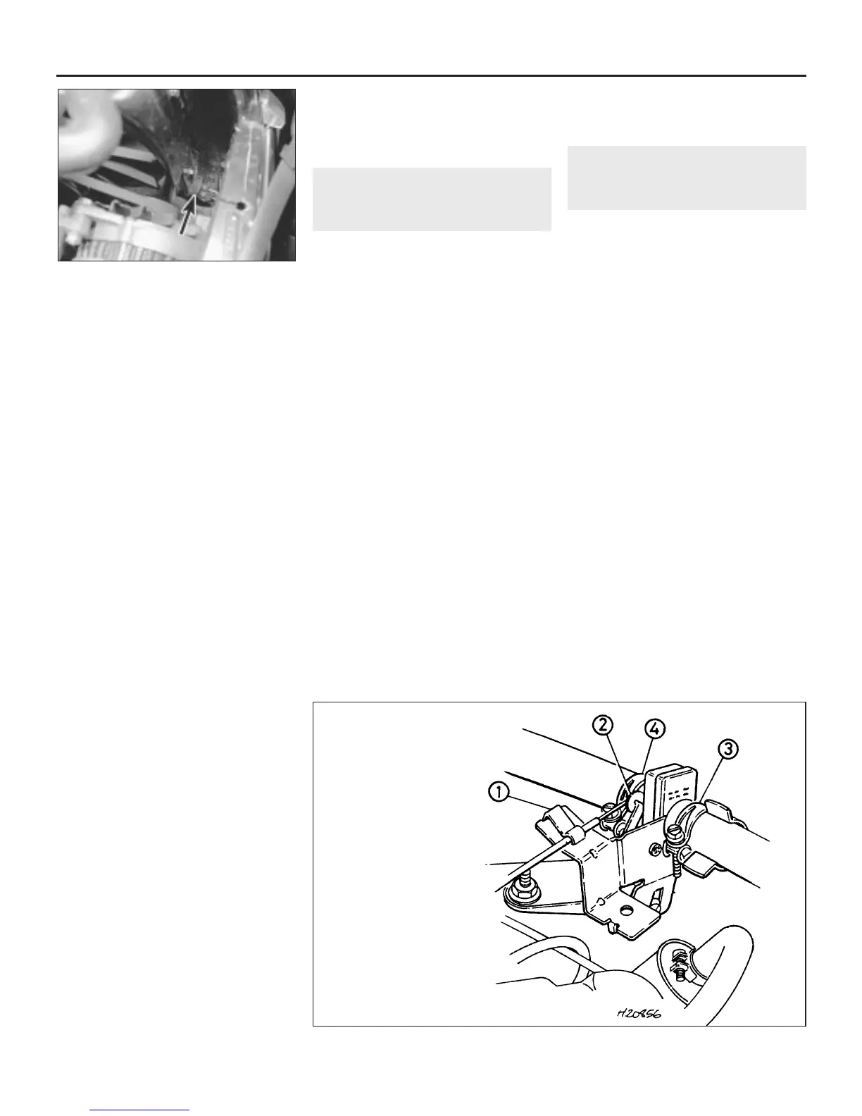
10.6 Heater valve - 1989-on
models
1 Outer cable retaining clip
2 Inner cable attachment
3 Coolant hose clip
4 Coolant hose clip
 Loading...