5 Disconnect the heater switch wires from the
switch.
6 Undo and remove the two nuts or screws
which secure the auxiliary switch panel to the
centre of the parcel shelf.
7 Draw the switch panel forward and unscrew
the choke cable retaining nut, or extract the
retaining clip (according to type) from the rear
of the panel.
8 Pull the complete cable through the
bulkhead grommet and switch panel, into the
passenger compartment. Recover the
retaining nut and lockwasher from the end of
the cable.
Refitting
9 To refit the cable, slide it through the slot in
the switch panel and then place the nut and
washer over the cable.
10 Insert the cable through the bulkhead
grommet and through to the engine
compartment.
11 Screw on and fully tighten the choke
cable retaining nut or refit the clip then refit
the switch panel. Position the word LOCK on
the cable knob at the top to ensure correct
operation in use. Reconnect the heater switch
leads and refit the heater securing screws.
12 Engage the other end of the cable into the
support bracket and the inner cable into the
trunnion on the choke linkage.
13 Ensure that the choke cable is pushed
fully in, ie in the “off” position, then tighten the
retaining screws on the support bracket and
cable trunnion. Ensure that there is 1.5 mm of
free play on the cable before the cable starts
to operate the choke linkage.
14 Refit the air cleaner, reconnect the battery
and, where applicable, refit the centre console
retaining screws.
6 Electric fuel pump - testing,
removal and refitting
2
Note: Observe the precautions in Section 1
before working on any component in the fuel
system.
Testing
1 To test the fuel pump, disconnect the fuel
supply hose at the top of the carburettor float
chamber and immerse the end of the hose in
a clean glass jar. With the ignition switched on
there should be a steady flow of petrol from
the end of the hose accompanied by a regular
ticking noise from the pump.
Warning: Carry out this operation
in a well ventilated area and take
great care not to splash fuel onto
hot engine components.
2 A rapid irregular ticking noise accompanied
by a mixture of fuel and air bubbles flowing
from the hose is indicative of an air leak on the
suction side of the pump (ie in the pipe
between the pump and fuel tank). This will
ultimately lead to fuel starvation and cutting
out or misfiring if not corrected.
3 No fuel flow from the supply hose indicates
a fault in the pump (perforated diaphragm,
dirty contact points etc), or a break in the
electrical supply to the pump. If the electrical
supply to the pump is sound but the pump is
still not functioning, it should be taken to an
auto-electrician for inspection and possible
repair, or replaced with an exchange unit.
Repair kits are unlikely to still be available
from normal sources so an exchange unit may
be the only alternative.
Removal
4 Disconnect the battery negative lead.
5 Chock the front wheels then jack up the
rear of the car and support it on axle stands
(see “Jacking and vehicle support”).
6 Working under the car, disconnect the earth
lead and the electrical supply wire from their
terminals on the pump body.
7 Prepare to squeeze the rubber portion of
the petrol pipe leading from the tank with a
self-gripping wrench or similar tool, to ensure
that the minimum amount of fuel is lost when
the inlet pipe is removed from the pump. Plug
the end of the pipe with a bolt or metal rod of
suitable diameter immediately it is
disconnected.
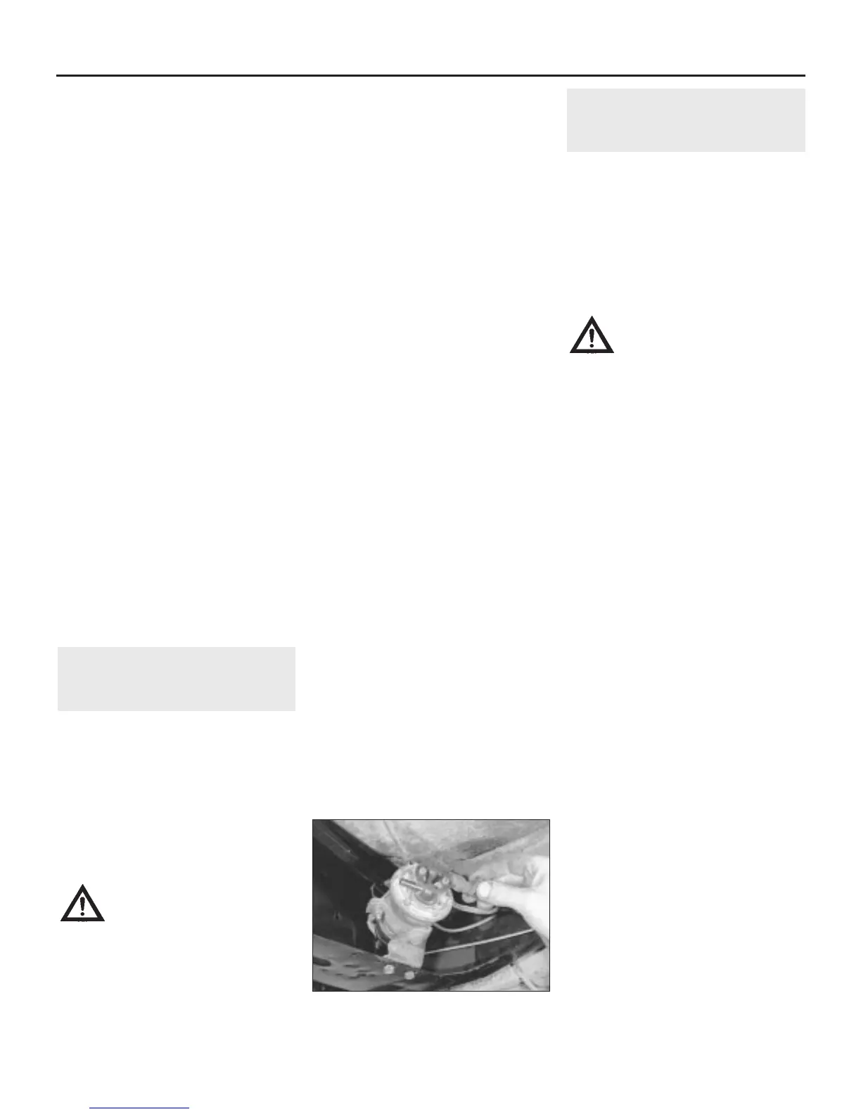
8 Remove the inlet and outlet fuel pipes by
undoing the retaining clip screws and easing
the pipes off the pump nozzles (see
illustration). Remove the vent pipe
connector, if fitted, at this stage.
9 Undo and remove the two nuts, bolts and
spring washers securing the pump bracket to
the subframe and lift off the pump assembly,
complete with bracket and clamp.
10 To separate the pump from the bracket,
slacken the clamp bolt and slide the pump out
of the clamp.
Refitting
11 Refitting is the reverse sequence to
removal, bearing in mind the following points:
a) Arrows on the pump body indicate the
correct locations of the inlet and outlet
pipes. Ensure that these are fitted
correctly and that the pump is installed
with the outlet pipe at the top.
b) Ensure that the electrical leads,
particularly the earth, are clean and that a
correct connection is made.
7 Mechanical fuel pump -
testing, removal and refitting
2
Note: Observe the precautions in Section 1
before working on any component in the fuel
system.
Testing
1 To test the fuel pump, disconnect the fuel
supply hose at the top of the carburettor float
chamber and immerse the end of the hose in
a clean glass jar. With an assistant cranking
the engine on the starter, regular spurts of fuel
should be ejected as the engine turns.
Warning: Carry out this operation
in a well ventilated area and take
great care not to splash fuel onto
hot engine components.
2 If the pump does not operate satisfactorily,
it should be renewed. The AUF 700 series
pump fitted to early models may be
dismantled for inspection, but repair kits are
unlikely to still be available from normal
sources. The AUF 800 series pump fitted to
later models is a sealed unit and cannot be
dismantled.
Removal
Note: The fuel pump used on later models
(1985-on) is different in appearance to those
used previously, but is fully interchangeable. A
modified kickdown rod will be required if a
new type pump is fitted to older vehicles with
automatic transmission. Details of the rod
fitment should be obtained from your dealer.
3 Disconnect the battery negative lead.
4 To provide greater access, remove the air
cleaner, as described in Section 2.
5 Slacken the pipe clip screw on the outlet
pipe connection and draw it off. Have a small
container handy to collect what little fuel may
drain from the pipe.
6 In all Saloon models, if the tank is more
than half full, the fuel will drain from the tank
under gravity when the fuel pump inlet pipe is
disconnected, so provide for this situation by
fitting a suitable clip or bung in the pipe if
necessary. On all other models the tank is
below the pump level, so this problem will not
occur. Slacken the pipe clip screw on the inlet
pipe connection and draw it off.
7 Slacken the two nuts which hold the pump
to the crankcase on two studs through the
lower body.
8 Ease the pump away from the crankcase
slightly and release the insulating block and
its two sealing gaskets. If they are stuck,
carefully prise them off the crankcase using a
knife or thin screwdriver. Now lift off the
pump, insulating block and gaskets.
Refitting
9 Refitting the pump is the reverse sequence
to removal bearing in mind the following
points:
a) Ensure that the mating faces of the pump
and crankcase are thoroughly clean and dry.
4A•6 Fuel system - carburettor engines
6.8 Removing the fuel outlet pipe from the
electric pump
 Loading...