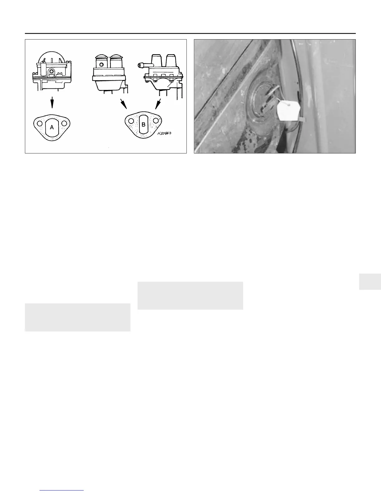
b) Ensure that the correct insulator block is
used according to pump type. The
insulator block fitted to the 700 series
pump is different from the insulator block
fitted to 800 series and AZX series pumps
(see illustration). The 700 series pump
requires an insulator block with a large
inner aperture, whereas the 800 series
and AZX pumps require an insulator block
with a small aperture in order to retain the
pump lever pivot. If the wrong insulator
block is fitted, there is a possibility of the
pivot and lever dropping into the
sump/transmission.
c) Use new sealing gaskets on either side of
the insulating block but make sure that
the original thickness is maintained
otherwise the pump operation may be
affected.
8 Fuel gauge sender unit -
removal and refitting
2
Note: Observe the precautions in Section 1
before working on any component in the fuel
system.
Removal
Saloon models
1 Disconnect the battery negative lead and
remove the fuel gauge wires from their
attachments to the sender unit mounted in the
side of the tank (see illustration).
2 On early models, unscrew the screws which
hold the gauge unit to the tank carefully, and
lift the complete unit away, ensuring that the
float lever is not bent or damaged in the
process.
3 On later models, using crossed
screwdrivers, remove the fuel gauge sender
unit by turning the locking ring through 30º
and lifting away. Carefully lift the unit from the
tank, ensuring that the float lever is not bent
or damaged in the process.
Estate, Van and Pick-up models
4 Refer to Section 9 and remove the fuel tank
from the car.
5 Removal and refitting of the sender unit
now follows the procedure described for
Saloon models.
Refitting
6 Refitting the unit is the reverse sequence to
removal. To ensure a fuel-tight joint, scrape
both the tank and sender unit mating flanges
clean, and always use a new joint gasket and
a suitable gasket sealer.
9 Fuel tank - removal and
refitting
2
Note: Observe the precautions in Section 1
before working on any component in the fuel
system.
Saloon models except Cooper S
Removal
1 Before the tank can be removed, it must be
drained of as much fuel as possible. To avoid
the dangers and complications of fuel
handling and storage, it is advisable to carry
out this operation with the tank almost empty.
Any fuel remaining can be drained as follows.
2 Disconnect the battery negative lead.
3 Using a hand pump or syphon inserted
through the filler neck, remove any remaining
fuel from the bottom of the tank. Note: A
number of earlier models were fitted with a
fuel tank incorporating a combined drain plug
and tube. Access to this is from below the car,
using a long box spanner. In all cases carry
out the draining or siphoning operation in a
well ventilated area, never in a garage or over
an inspection pit.
4 Remove the spare wheel from its location in
the luggage compartment.
5 Disconnect the wiring from the fuel gauge
sender unit located on the side of the tank
(see illustration).
6 If the car is fitted with an electric fuel pump,
slacken the clip and detach the fuel inlet hose
from the pump inlet nozzle. Collect any
remaining fuel in a suitable container.
7 When the tank is empty, slacken the clip
and detach the fuel hose from the front of the
tank.
8 Detach the fuel tank breather pipe and
remove the filler cap.
9 Undo and remove the tank securing strap
bolt and carefully manoeuvre the fuel tank
from the luggage compartment.
10 If the tank is contaminated with sediment
or water, remove the fuel gauge sender unit as
described in Section 8 and swill the tank out
with clean fuel. If the tank is damaged or
corroded it should be renewed. However, in
certain cases it may be possible to have small
leaks or minor damage repaired. Seek the
advice of a Rover dealer or suitable specialist
concerning tank repair.
Refitting
11 Refitting is the reverse sequence to
removal.
Estate, Van and Pick-up models
12 Disconnect the battery negative lead.
13 Chock the front wheels then jack up the
rear of the car and support it on axle stands
(see “Jacking and vehicle support”).
14 Remove the tank filler cap then, from
underneath the car, undo and remove the
drain plug, allowing the fuel to drain into a
suitable container. Do this in a well ventilated
area, not in a garage or over an inspection pit.
When drained, refit the drain plug and washer
securely.
Fuel system - carburettor engines 4A•7
4A
7.9 Mechanical fuel pump insulator block types
A 700 series type B 800 and AZX series type
8.1 Electrical leads at the fuel gauge sender unit on the side of the
tank (Saloon models)
 Loading...