Pomona, CA Clemmons, NC Nashville, TN
Tel: 908-355-7995 www.hayward-pool.com
USE ONLY HAYWARD GENUINE REPLACEMENT PARTS
15
Table 5: Allowable Water Flow Rate Range
Model
Minimum Flow
Rate (GPM)
Maximum Flow
Rate (GPM)
H13510
ABG135
20 125
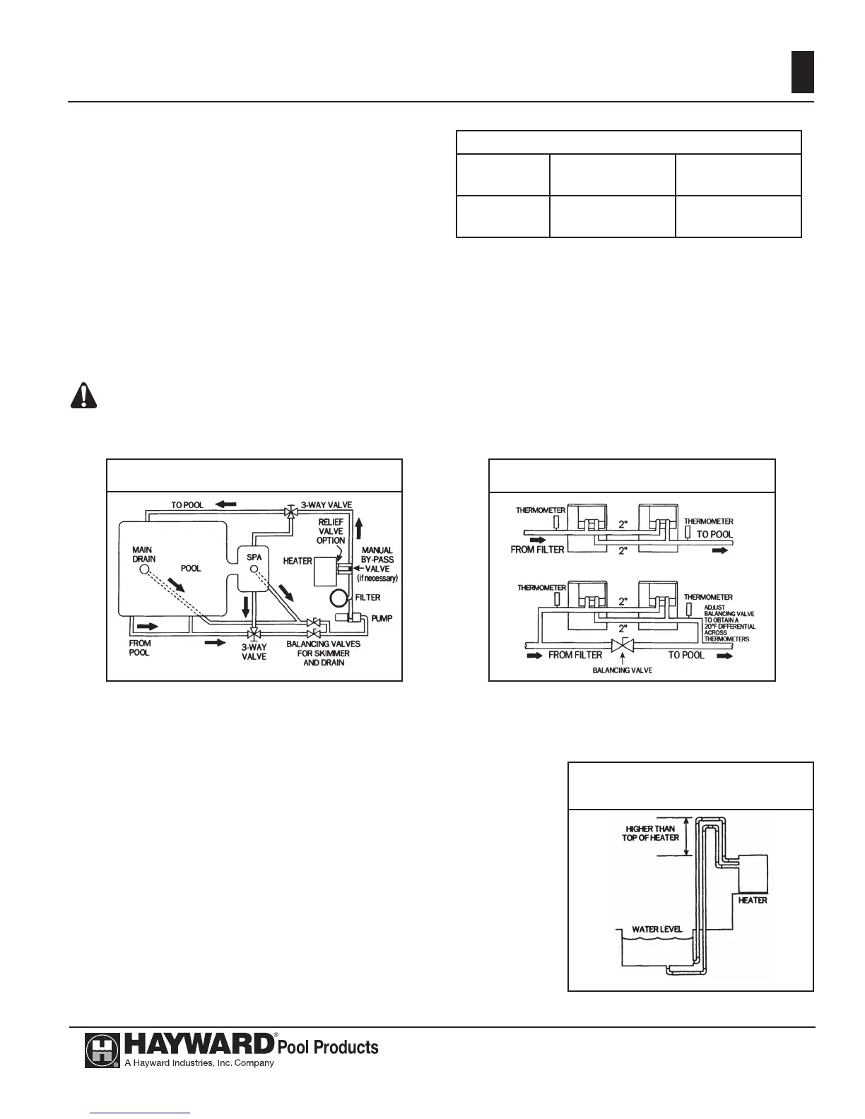
Figure 07: Typical plumbing to pool
Figure 0707 illustrates a typical pool piping diagram and layout for the pool equipment.
Figure 0808 illu
strates a multiple heater installation for very large pools with and without a manual
bypass valve.
Figure 08: Multiple heater system
INSTALLATION ABOVE/BELOW WATER SURFACE:
If the heater is installed less than three (3) feet above the surface of
the pool/spa water, install eyeball fi ttings or directional fl ow fi ttings on
the end of the return water line to the pool/spa to create adequate back
pressure at the heater to operate the pressure safety switch when the
fi lter pump is running.
If the heater is installed more than three (3) feet above the surface
of the pool/spa water, install a loop as shown in Figure 0909 to prevent
drainage of water in the heater during a fi lter change.
For installation below the pool/spa surface, refer to Section III.
Figure 09: Heater installation
above pool/spa
is within the range for the heater. See Table 5. The
minimum fl ow rate is to be calculated or measured with
the in-fl oor cleaning system in use, if the pool is so
equipped, as well as any other jets or other demands on
the water fl ow.
If the normal pump and fi lter system fl ow rate
exceeds 125 gpm then a manual bypass valve must be
installed as show
n in Figure 06. Damage caused by fl ow
rates outside this range will void the manufacturer’s warranty.
The installation is as follows:
1.
Install a fl ow meter on the outlet line of the heater.
2. Adjust the manual bypass valve until the fl ow rate is within the fl ow rate range specifi ed for the heater.
3. Once the valve is set, note the position and remove the valve handle to prevent further adjustment.
ATTENTION: Improperly adjusted manual bypass valves will result in damage to the heater if the fl ow
rates are not maintained as specifi ed in Table 5 under all operating conditions. The heat exchanger will
fail and this damage will not be covered under the Hayward warranty.
 Loading...