Pomona, CA Clemmons, NC Nashville, TN
Tel: 908-355-7995 www.hayward-pool.com
USE ONLY HAYWARD GENUINE REPLACEMENT PARTS
39
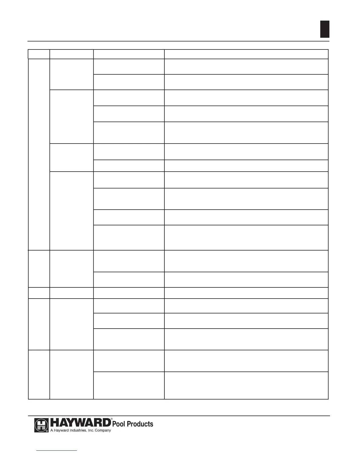
Figure 22: TROUBLESHOOTING
Code Fault Diagnosis Step Remedy
None
Heater will not
power up
1. Ensure fi eld power supply
to heater is turned on.
Measure for fi eld supply voltage across primary terminals of
transformer.
2. Check for defective
Transformer.
If 120 VAC is present at transformer primary, check secondary for 24
VAC. If not present, replace transformer.
Low voltage
circuit fault.
1. Check for faulty Control
Module wiring.
Inspect Control Module wiring. Ensure all plugs are securly fastened
to Control Module. If OK, proceed to step 2.
2. Verify low voltage input
to Control Module.
Verify 24VAC across R and C terminals on Control Module. If not
OK, replace harness. If OK, procced to step 3.
3. Verify that F1 Fuse on
Control Board is not open.
Remove F1 fuse from fuseholder. Measure continuity across fuse.
If OK, replace Control Module. If fuse is open, proceed to section
titled ‘‘Open Fuse on ignition board’’.
Low voltage
fault
1. Check for faulty
Transformer wiring.
Inspect Transformer wiring. Ensure insulation on wiring is not worn.
If OK, proceed to step 2.
2. Defective Transformer
Replace Transformer.
Open Fuse on
ignition board
1. Check for faulty Gas
Valve wiring.
Inspect Gas Valve wiring. Ensure insulation on wiring is not worn.
If OK, proceed to step 2.
2. Verify that Gas Valve is
not defective.
Measure for resistance across Gas Valve terminals and between each
terminal and ground. If short exists, replace Gas Valve. If OK,
proceed to step 3.
3. Check for faulty Control
Module wiring.
Inspect Control Module wiring. Ensure insulation on wiring is not
worn. If OK proceed to step 4.
4. Control Module is
defective.
Replace Control Module.
bD
Bad Board or
Secondary High
Vo l tage Fault
1. Check for defective
Harness.
Disconnect plug from E10 connector of Contol Module. Measure
for 120VAC across pins 1 and 3 of Plug on Harness. If OK, replace
Control Module. If not OK, replace Harness.
2. Check for defective
Transformer.
If 120 VAC is present at transformer primary, check secondary for 24
VAC. If not present, replace transformer.
EE
Bad Board 1. Defective Control Module
Replace Control Module.
CE
Communicat-
ion Error
between
Control Module
and Display
Interface
Assembly
1. Disconnect and then re-
connect power to heater.
2. Check for faulty wiring or
connection.
Inspect Display Interface Wiring. Ensure Display Interface Plug is
securely attached to Control Module. If OK, proceed to step 3.
3. Control Module and/or
Display Interface Assembly
are defective.
Replace Control Module and/or Display Interface Assembly.
PF
Supply power
fault
1.Check polarity of electrical
outlet powering the heater.
If neutral and line voltage wires are reversed on the electrical outlet,
have an electrician remedy this issue. (Swap the line and neutral
wires.) If line and neutral wires are correct, proceed to step 2.
2. Check that the ground
wire is connected in the
electrical outlet powering
the heater.
If ground wire is not connected, have an electrician remedy this
issue. If ground wire is conected, proceed to step 3.
 Loading...