Page 4 of 12 Pro-Grid
TM
VERTICAL D.E. SERIES FILTER ISDE2423 REV C
GENERAL INFORMATION
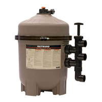
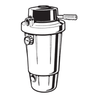
Your Hayward Pro-Grid
TM
Vertical Grid D.E. Filter combines superior water filtration with ease of operation and totally
corrosion-free construction. It uses diatomaceous earth (D.E.), which is the most efficient dirt remover and filter medium
known.
The D.E., which is usually fed through the skimmer at initial start-up, uniformly coats the curved vertical filter elements
that are covered with a custom fitted monofilament polypropylene filter cloth. As pool water is pumped through the
control valve into the bottom of the filter tank, the D.E. surface, or coating, filters out even the minutest particles
resulting in clear, clean, sparkling water.
After a period of time, the accumulated dirt in the filter causes a resistance to flow, the pressure rises, and flow
diminishes. This means the dirt holding capacity of the D.E. has been reached, and it is time to clean (backwash) your
filter. With the control valve in the back wash position, the water is automatically reversed through the filter, flushing
trapped dirt, debris and D.E. out the waste line. Once the filter is backwashed (cleaned) of D.E. and dirt, the control
valve is manually re-sequenced to filter position and a fresh charge of D.E. is added to resume normal filtering.
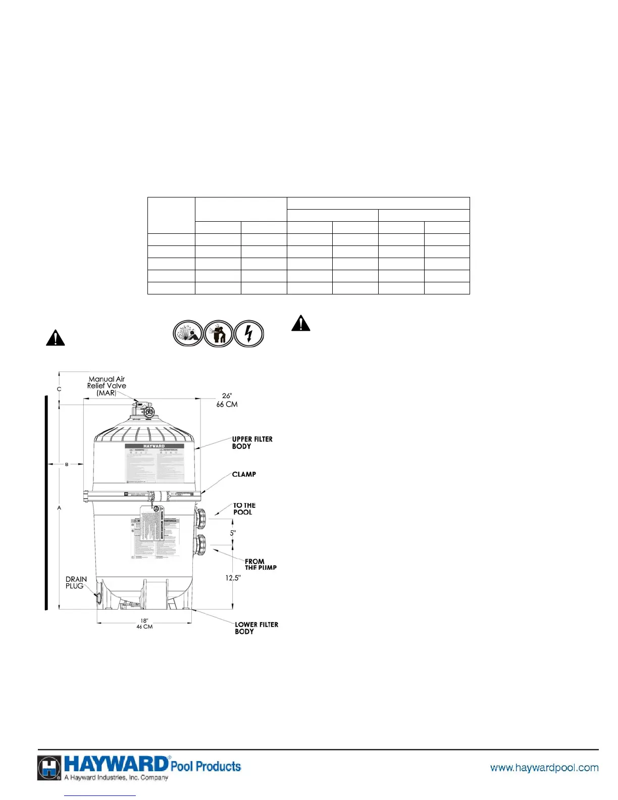
REQUIRED CLEARANCE
A
“B” SIDE “C” ABOVE
IN CM IN CM IN CM
DE2420 32.0 81 18 46 15 38
DE3620 34.1 87 18 46 16 41
DE4820 40.1 102 18 46 18 46
DE6020 46.1 107 18 46 22 56
DE7220 52.0 132 18 46 25 63
INSTALLATION
WARNING
Only simple tools (screwdriver and wrenches), plus pipe sealant
for plastic adapters, are required to install and/or service the
filter.
1. The filter system should be installed on a level concrete slab
or other rigid base. Select a well drained and vented area,
one that does not flood when it rains. Position the filter so
that the piping connections, and winter drain are convenient
and accessible for operation, service, maintenance and
winterizing.
2. Position filter so the filter will drain by gravity.
3. If practical, place pump and filter in the shade to shield it
from continuous, direct heat from the sun.
4. Assemble appropriate Filter Control valve (See Page 10 for
selection) to filter. Lubricate the O-ring first (we recommend
using Jack’s 327 Lubricant). Align the two (2) valve pipe
connections, with O-rings in place, with the two openings in
the side of the filter tank and press in firmly. Secure the
assembly to the tank connections with the two bulkhead lock
nuts. Do not over-tighten.
5. Connect the pool suction plumbing between the skimmer,
pool outlet and the pump.
6. Install the pool return plumbing.
7. If pressure gauge is not installed, apply Teflon tape to the
gauge threads and carefully screw the gauge into the gauge
adapter assembly.
8. Do not locate pump controls over or near filter.
9. Verify water discharge from the filter manual air relief valve is
directed away from electrical devices
USE ONLY HAYWARD GENUINE REPLACEMENT PARTS
This product should be installed and serviced only by a
ualified
rofessional.