Do you have a question about the HBD PV500-0007M1 and is the answer not in the manual?
Defines key safety terms like Danger and Warning, and explains warning symbols used throughout the manual.
Covers essential safety rules for handling, installation, and operation, including electrical safety and environmental considerations.
Details safe procedures for commissioning, maintenance, component replacement, and scrap treatment of the inverter.
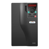
Guides on inspecting the product after delivery, understanding the name plate, type designation, and general specifications.
Lists detailed electrical and performance specifications for different inverter models, including input/output characteristics and shape cases.
Covers environmental requirements, installation site conditions, and physical mounting procedures for the inverter to ensure proper operation.
Specifies conditions for the installation site, including temperature, humidity, running environment, pollution, altitude, and vibration.
Describes how to orient the inverter during installation and the methods for mounting it, including wall and rail options.
Explains the main circuit terminals for AC input, DC PV input, AC output, and safety grounding, along with wiring diagrams.
Provides specific wiring instructions and internal wiring diagrams for single-phase motor output models, including capacitor connections.
Details the functions of control circuit terminals, including power supply, digital inputs (DI1-DI4), and communication interfaces.
Explains RS485 communication terminals and the functions of relay outputs (RO1) for signaling and control purposes.
Introduces the inverter's keypad, its role in control, and the types of states it displays, such as stopping, running, and fault.
Describes how to view stopping and running parameters, interpret fault codes, and enter parameter editing mode.
Guides on how to change inverter function codes and set up password protection for security, ensuring proper operation.
Explains how to use specific function codes (P17) to view the inverter's real-time operating status and parameters.
Details essential inspections before powering on, the trial run process, and basic parameter setting procedures.
Covers PI adjustment for water yield and specific settings for optimizing single-phase motor performance under various conditions.
Explains fundamental parameters for basic inverter functions like speed control, run command channels, and frequency limits.
Covers parameters for speed control, motor identification, and basic settings for optimal motor operation.
Details SVPWM control, V/F curve settings, torque boost, slip compensation, and single-phase drive modes for performance optimization.
Covers voltage ratio settings, function assignments for input terminals (HDI, DI1-DI5), and selections for relay outputs (RO1, RO2).
Configures delays for relay outputs and defines functions for keypad buttons like QUICK/JOG.
Covers keypad command shifting, STOP/RST functions, boost module monitoring, and detailed fault history logs.
Details fault reset, phase loss protection, frequency decrease, PV inverter functions, and comprehensive water level control settings.
Covers weak light alarms, MPPT voltage settings, input switching logic, pump ratings, PV undervoltage, model selection, and state viewing.
Details boost module communication, voltage/current loop parameters, and software version for enhanced control.
Guides users on how to obtain product support, provide feedback on manuals, and access online documentation.