Do you have a question about the HBK U3 and is the answer not in the manual?
Operate the force transducer strictly as described in the mounting instructions and relevant safety regulations.
Potential hazards arising from inappropriate installation or operation by untrained personnel.
Minimize residual dangers by addressing safety engineering considerations in force measurement techniques.
Explanation of document markings for safety warnings, important information, and tips.
Information on statutory marking requirements for product symbols and waste disposal.
Lists the U3 force transducer, mounting instructions, and test report as part of the scope of supply.
Details accessories like adapters and knuckle eyes for mounting, along with their order numbers.
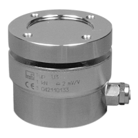
Force transducer suitable for tensile/compressive forces; requires careful handling to prevent damage.
The measuring element is a stainless steel spring with strain gauges arranged to detect forces.
The housing has a thin base, requiring protection against mechanical damage and careful handling.
Maintaining the nominal temperature range is crucial for optimal measurement results and accuracy.
Avoid extreme humidity and prevent dust/dirt accumulation to maintain transducer performance.
Handle with care, avoid overload, and protect against welding currents during installation.
Ensure force direction is optimal, minimize moments, and understand transverse force capacity.
Mount directly for axial forces, ensuring no axial play; pre-stress for dynamic sustained loads.
Screw directly onto structural elements for axial forces in tensile and compressive directions.
Mount with an adapter and knuckle eye for tensile loading, preventing torsional moments.
Screw the correct adapter and knuckle eye into the adapter until it stops.
Unscrew knuckle eye, align it, and load with nominal load before final tightening.
Secure the knuckle eye assembly by tightening the lock nut using the adapter's flat.
Details the process of mounting the transducer using two knuckle eyes for tensile loading.
Screw the correct adapter and knuckle eye into the adapter, then align and secure.
Ensure correct shaft diameter and fitting size for proper mounting with knuckle eyes.
Select the shaft diameter as recommended to prevent bearing damage and knuckle eye breakage.
Maintain correct play between knuckle eye and shaft bearing to prevent deformation and damage.
Apply rules of thumb and recommendations to determine the correct play for optimal performance.
Use shielded cables, maintain distance from power lines, and ensure proper grounding and shielding.
Steps for accessing the cable screen, attaching it to the housing frame, and to the connector.
Presents key specifications including nominal force, accuracy class, sensitivity, and environmental effects.
Provides dimensional drawings and a table for U3 transducers with capacities from 0.5 to 20 kN.
Provides dimensional drawings and a table for U3 transducers with capacities of 50 and 100 kN.
Details dimensions for the adapter accessory, including tables for various force ranges and weights.
| Brand | HBK |
|---|---|
| Model | U3 |
| Category | Industrial Equipment |
| Language | English |