45
WE2110
HBMA2181-1.0 de/en
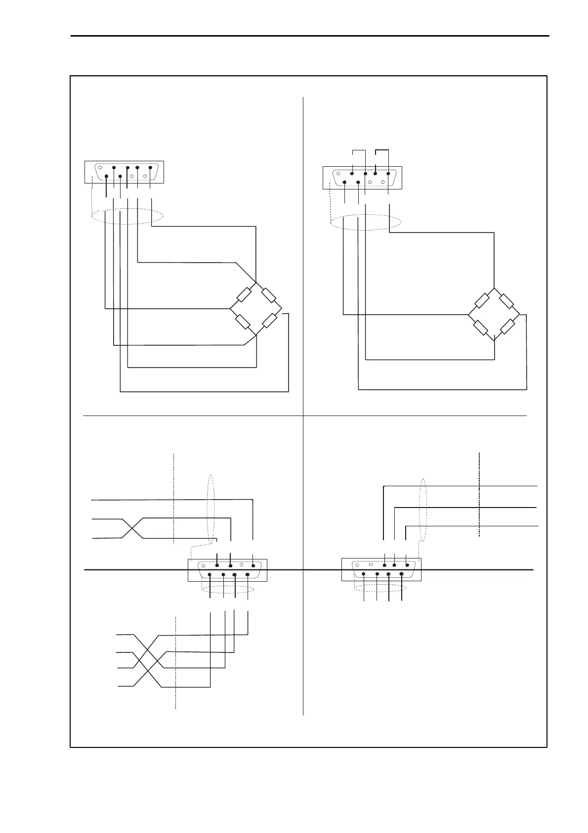
Connection diagrams
DB9 − F
RS−422/485
6
7
23
5
9
8
Serial 1
DB9 − M
1
2
3
4
9
8
Load cell 6-wire
DB9 − F
6
7
3
4
5
9
8
Serial 2
DB9 − M
1
2
3
4
9
8
1−Excitation+
2−Sensor circuit+
9−Signal+
4−Sensor circuit−
3−Excitation−
8−Signal−
Screen connected to
backshell
1−Excitation+
9−Signal+
3−Excitation−
8−Signal−
(RS-232 or RS-422) (RS-232 or RS-422)
Gnd
TxD
RxD
Gnd
TxD
RxD
WE2110 RS-232PC COM1 WE2110 RS-232 Printer
TxD
DTR
Gnd
TxD
DTR
Gnd
Select in menu
<SERIAL><BITS>
Host
TB
TA
RB
RA
TB
TA
RB
RA
Pin 6...9 are connected to the same pins
of Serial 1 in the WE2110.
If RS-422/485 is selected Serial 2 is not active!
See description of commands for more infor-
mation to realize a bus system.
Load cell 4-wire
Screen connected to
backshell
*)
*)
*)
*)
*)
View from the soldering side of the plugs included in the scope of supply
 Loading...