Pump Stroke Counter
User’s Manual – 2100, Rev D | Aug 2014
12
5.C Main PCB / Debounce:
The user can also conduct a similar test to the Sensor tests above; directly on the PCB or
Debounce Board found within the Control Head. Using the pin details listed below, the user can
simulate strokes. The test will allow the user to determine whether a new PCB or Debounce
Board is needed. If the system being tested has an available spare connection on the PCB, the
user can move the signal over to test on the input another pump. For example, if the System is
a 3 pump unit and pump 2 isn’t displaying correctly, move the white wire to pump 4 to test.
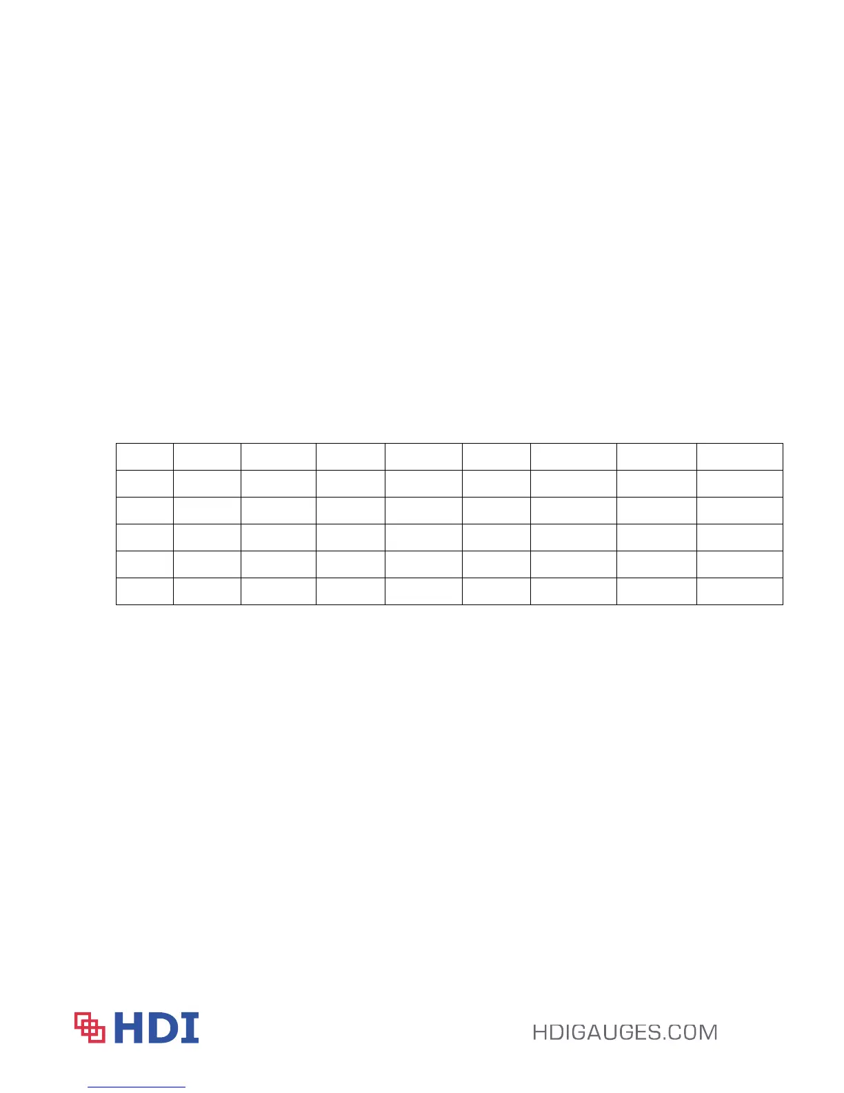
Each System’s pump configuration is different. Please review the table below which identifies
each System’s wiring configuration for testing. Test either board by tapping the faulty pump’s
wires with the common. For example, to test Pump 2 on a 2 Pump System, tap the pins B and
C.
1 Pump
1 Pump 2 Pump
2 Pump 3 Pump
3 Pump 4 Pump 4 Pump
Pin A Black P1 A - B Black P1 A - C
Black P1 A – D Black P1 A – E
Pin B White White P2 B - C
White P2 B – D White P2 B – E
Pin C Green Red P3 C – D Red P3 C – E
Pin D Green Common P4 D – E
Pin E Green
Section 6 – Options
Backlight and External Power
The System can be modified to add backlighting and the unit can be powered by an external 12
or 24VDC power source provided basic precautions and barriers are used. Please note, these
two options can be carried out in the field after the fact but are costly to do so as the internal
components would be replaced.
Output
HDI offers dual proximity sensors in one all thread stem allowing the signals to be split to the
Control Head and an HMI or secondary remote display.