EasyManua.ls Logo

Heat & Glo LOGS-6000G User Manual

Heat & Glo LOGS-6000G
2 pages
To Next Page IconTo Next Page
Page #1 background imageLoading...
Page #1 background image
STEP 2.
Place the metal grate on top of the burner.
Position the legs of the grate into the forward set
of indentations in the burner top. Make sure that
grate is all the way forward. See Figure 2.
STEP 1.
CAUTION: Logs are fragile! Carefully remove
the logs, grate and supporting cardboard from
the inside of the replace See Figure 1.
If the gas logs have been factory installed they
should not need to be positioned. If the logs have
been packaged separately, refer to the following
instructions.
Figure 2
Figure 4 Top View
1
1
2
2
3
3
4
4
5
5
STEP 3.
Log #1 (SRV2103-107):
Place the log on the burner so the cutout in the
log goes around the hump in the burner. The outer
legs of the log should self center on the sides of
the burner. Pull the log forward. The ramp shape
in the bottom of the log sits fully against the ramp
shape molded into the burner. The right side of
the log will touch the smaller hump. There will
be a 1/4 inch or so gap around the hump. See
Figures 3 and 4.
1
1
Figure 1
1
1
Figure 3 Front View
Log Set Assembly: LOGS-6000G
Models: 6000G, 6000GBV, 6000GCF
LOG PLACEMENT
INSTRUCTIONS
Heat & Glo • 6000G • 2103-910 Rev. C • 8/06
HUMP
SMALLER
HUMP
INDENTATIONS
Question and Answer IconNeed help?

Do you have a question about the Heat & Glo LOGS-6000G and is the answer not in the manual?

Heat & Glo LOGS-6000G Specifications

General IconGeneral
Log MaterialCeramic Fiber
Vent TypeVented
Product TypeLog Set
Fuel TypeGas
BTU RangeUp to 60, 000 BTU
Ignition TypeElectronic Ignition

Summary

Log Placement Instructions

Step 1: Log Handling and Grate Placement

CAUTION: Logs are fragile! Carefully remove logs, grate and supporting cardboard. See Figure 1.

Step 2: Grate Positioning

Place metal grate on burner. Position legs into forward indentations. Ensure grate is all the way forward. See Figure 2.

Step 3: Log #1 Placement

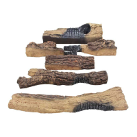
Place Log #1 on burner with cutout around hump. Outer legs self-center; pull forward. Log ramp against burner ramp. Gap around hump.

Step 4: Log #2 Placement

Place Log #2 on left side of Log #1. Slot fits over tab on Log #1. Left end behind ember cluster. See Figures 5 & 6.

Step 5: Log #3 Placement

Place Log #3 on burner surface in front of hump. Square groove over second grate tine from left. Slide back against hump.

Step 6: Log #4 Placement

Place Log #4 on right side of Log #1. Slot fits over tab on Log #1. Other end rests on grate, against second tine from right.

Step 7: Log #5 Placement

Place Log #5 in front of Log #3. Notch in bottom rests over center tine on grate. Log should not cover any ports.

Related product manuals