EasyManua.ls Logo

Heat & Glo LOGS-6000GL User Manual

Heat & Glo LOGS-6000GL
3 pages
To Next Page IconTo Next Page
Page #1 background imageLoading...
Page #1 background image
Heat & Glo • 6000GL • 2102-910 Rev. C • 8/06
1
STEP 2.
Place the metal grate on top of the burner.
Position the legs of the grate into the forward
set of indentations in the burner top. The grate
should not cover any ports in the burner.
STEP 1.
CAUTION: Logs are fragile! Carefully remove
the logs, grate and supporting cardboard from
the inside of the replace See Figure 1.
If the gas logs have been factory installed they
should not need to be positioned. If the logs have
been packaged separately, refer to the following
instructions.
1
1
2
2
3
3
4
4
5
5
STEP 3. Log #1 (SRV2102-010): Log #1 is the back burning log. The air shutter in the end of the burner tube goes
over the brass ori ce located behind the main burner. The log should be parallel to back refractory.
1
1
1
1
6
6
2
2
2
2
STEP 4. Log #2 (SRV2102-101): Place log #2 on top of log #1. The bottom side of this log has a slot in it that goes
over the left metal tab sticking up out of the top of log #1. The left end of this log sits on the burner surface.
Log Set Assembly: LOGS-6000GL
Models: 6000GL-IPI-R, 6000GL-IPI-S
LOG PLACEMENT
INSTRUCTIONS
HUMP
HUMP
Figure 1
Figure 2. Front View
Figure 4. Front View
Figure 5. Top View
Figure 3. Top View
Question and Answer IconNeed help?

Do you have a question about the Heat & Glo LOGS-6000GL and is the answer not in the manual?

Heat & Glo LOGS-6000GL Specifications

General IconGeneral
BrandHeat & Glo
ModelLOGS-6000GL
CategoryFireplace Accessories
LanguageEnglish

Summary

Log Placement Instructions

Step 1: Initial Removal and Grate Placement

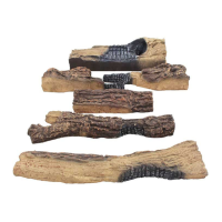
Carefully remove logs and grate. Position the metal grate on the burner without covering ports.

Step 2: Placing Log #1

Place the back burning log (#1) over the brass orifice, parallel to the back refractory.

Step 3: Placing Log #2

Position Log #2 on Log #1, aligning its slot with the metal tab on Log #1.

Step 4: Placing Log #3

Place Log #3 on the burner, aligning its notch with the grate tine and resting against the hump.

Step 5: Placing Log #4

Place Log #4 on the burner, aligning its groove with the grate tine and sliding it forward.

Step 6: Placing Log #5

Place Log #5 on Logs #1 and #3, aligning its slot with the tab on Log #1 and its thin end on Log #3.

Step 7: Placing Log #6

Place Log #6 on Logs #5 and #4, resting on designated flat spots on both logs.

Related product manuals