Do you have a question about the Heat Controller DMH18SB-1 and is the answer not in the manual?
Guidelines for safe installation of the unit, covering electrical work and mounting.
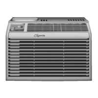
Details dimensions for indoor unit models.
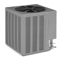
Details dimensions for outdoor units (9k, 12k models).
Explains symbols used to indicate warnings and notices.
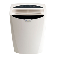
Highlights key features of the indoor and outdoor units.
Lists essential parts required for installation.
Lists necessary tools for the installation process.
Information about R-410A refrigerant and handling precautions.
Guidance on choosing optimal locations for indoor and outdoor units.
Specifies allowed piping lengths and elevation differences.
Instructions for securely mounting the indoor unit's installation plate.
Details on drilling the wall for piping connections.
Procedures for flaring copper pipes to prevent gas leakage.
Steps for connecting indoor unit piping and drain hose.
How to connect the drain hose to the indoor or outdoor unit.
Procedures for connecting outdoor unit piping.
Detailed steps for connecting power and control cables.
Important considerations before and during electrical wiring for the unit.
Steps to verify proper drainage and avoid issues.
How to route and secure piping and drain hose.
Explains the importance of removing air and moisture from the system.
Detailed steps for air purging using a vacuum pump.
Procedures for charging the system with refrigerant.
Instructions for installing batteries in the remote control.
Guidance on securely mounting the outdoor unit.
How to check system performance after test running.
Procedure for collecting refrigerant when moving or servicing the unit.
Explanation of various indicators and operational modes.
Explains the meaning of different indicators on the unit.
Information on error codes and how to check system diagnostics.
Detailed description of remote control buttons and functions.
Steps to detach the front grille from the indoor unit chassis.
Diagrams illustrating refrigerant flow for cooling and heating models.
Explains valve positions for different operations.
Procedure for charging the system with refrigerant after evacuation.
Analysis of cycle parts and potential causes of trouble.
Troubleshooting steps for electronic parts in the 9k model.
Troubleshooting steps for electronic parts in the 18k model.
Steps to diagnose issues when the remote controller is not working.
Troubleshooting for cases where the compressor or outdoor fan does not operate.
Troubleshooting for cases where the compressor or outdoor fan does not operate.
Steps to diagnose issues when the indoor fan is not operating.
Troubleshooting steps for a non-operational vertical louver.
Steps to diagnose and resolve communication errors between units.
Lists phenomena related to connector errors in the indoor unit.
Lists phenomena related to connector errors in the outdoor unit.
Detailed diagram of the indoor unit's electronic control components.
Electrical schematic for outdoor units (9k and 12k models).
Electrical schematic for outdoor units (18k and 24k models).
Wiring diagram for the indoor unit.
Wiring diagrams for outdoor units (9k, 12k, 18k, 24k models).
Diagrams showing display assembly layouts.
Shows locations of components on the indoor unit's main PCB assembly.
Technical specifications for cooling-only air conditioner models.
Technical specifications for cooling & heating air conditioner models.
| BTU | 18, 000 |
|---|---|
| Cooling Capacity | 18, 000 BTU |
| Energy Efficiency Ratio (EER) | 12.5 |
| Voltage | 208/230V |
| Phase | 1 |
| Refrigerant | R410A |
| SEER | 21 |
| Seasonal Energy Efficiency Ratio (SEER) | 21 |
| Weight (Indoor Unit) | 15 kg |
| Weight (Outdoor Unit) | 45 kg |
| Operating Temperature (Cooling) | 5°C to 48°C |
| Operating Temperature (Heating) | -15°C to 24°C |