Do you have a question about the Heat Controller MSS-009B/A and is the answer not in the manual?
Covers ON/OFF, temperature sensing/control, fan speed, auto wind, and airflow direction.
Details starting current control, time delay, defrost, and hot-start controls for system protection.
Explains Soft Dry, Sleep Mode, and Auto Air control functionalities.
Covers ON/OFF, Operation Mode Selection, and Fan Speed Selection buttons.
Details temperature display/setting and timer functions (selection, setting, cancel).
Covers Airflow Direction Control, Fan Operation Mode, and Reset functions.
Physical measurements for the indoor unit, including Width, Height, and Depth.
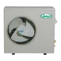
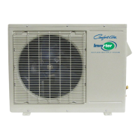
Physical measurements for the outdoor unit, including W, H, D, and L1-L10.
Diagram and specifications for the refrigeration cycle of cooling-only units.
Diagram and specifications for the refrigeration cycle of cooling & heating units.
Diagrams illustrating electrical connections for indoor units.
Diagrams showing electrical connections for cooling-only outdoor units.
Diagrams showing electrical connections for cooling & heating outdoor units.
Explains time delay safety, airflow direction, and cooling operation mode.
Details electronic control mode for auto operation, including cooling specifics.
Covers Soft Dry, Heating auto modes, and vertical louver auto operation.
Details compressor ON/OFF temperatures and operation diagram for Soft Dry.
Explains heating operation and hot-start control features with diagrams.
Details defrost control logic, timing, and outdoor pipe temperature conditions.
Describes operation diagrams for cooling and heating modes combined with sleep mode.
Explains forced operation, crank case heater coil control, and their conditions.
Lists test operations for indoor units based on key press counts.
Lists test operations for outdoor units based on key press counts.
Explains operation indicators, timer indicators, and buzzer sound meanings.
Details error codes, LED blinks, and unit operations for troubleshooting.
Covers important warnings, cautions, safety gear, and handling.
Details risks associated with wiring, transport, installation environment, and servicing.
Lists components provided with the unit for installation.
Covers selection of best locations for indoor and outdoor units, including rooftop.
Details maximum piping length and elevation limits for installation.
Instructions for attaching the wall plate using screws and ensuring alignment.
Guidance on drilling the hole for refrigerant pipes, including angle.
Covers cutting, deburring, flaring, and protecting copper pipes before connection.
Instructions for connecting tubes, drain hose, and cables, plus notes on insulation.
Details on tightening flare nuts, wrapping insulation, and handling tubing.
Instructions for routing tubing and cables for left-side installations.
Covers inserting cables, taping, and connecting pipings to the indoor unit.
Steps for setting pipings and mounting the indoor unit onto the installation plate.
Instructions for aligning and tightening flare nuts for piping connections.
Details on wiring, grounding, and using conduit tubes according to codes.
Provides an example of connecting the cable and important wiring warnings.
Step-by-step guide for preparing and attaching strand wiring to terminals.
Steps for removing the grille and checking water flow through the evaporator and drain hose.
Instructions for connecting wires to the control board and attaching the front grille.
Instructions for taping and forming pipes when the outdoor unit is lower than indoor.
Instructions for taping and forming pipes when the outdoor unit is higher than indoor.
Steps for preparing, leak testing, and purging the system using a vacuum pump.
Details on system evacuation, closing valves, and preparing for test run.
Instructions for preparing the remote controller and performing the initial unit test run.
Guidelines for anchoring the outdoor unit securely to prevent vibration and movement.
Procedures for checking refrigerant charge, ambient temperature, and pressure charts.
Describes the purpose of each button on the remote for cooling mode operation.
Describes the purpose of each button on the remote for heating mode operation.
Step-by-step guide to detach the front grille from the indoor unit chassis.
Instructions for disconnecting thermistors, connectors, and removing the control box.
Instructions for detaching the discharge grille from the chassis.
Steps for unhooking and removing the evaporator assembly from the indoor unit.
Steps for loosening screws and removing the fan from the motor shaft.
Instructions for picking up and removing the fan motor from its groove.
Step-by-step guide to detach the front grille from the indoor unit chassis for 18k/24k models.
Instructions for disconnecting components and removing the control box for 18k/24k models.
Instructions for detaching the discharge grille from the chassis for 18k/24k models.
Steps for unhooking and removing the evaporator assembly for 18k/24k models.
Steps for loosening screws and removing the fan from the motor shaft.
Instructions for picking up and removing the fan motor from its groove.
Guide to diagnosing issues based on temp differences, operating current, and pressure readings.
Diagnosing issues when the product fails to operate, checking power, connections, and PCB.
Diagnosing problems when the unit does not respond to the remote controller.
Diagnosing issues when the compressor or outdoor fan does not drive.
Diagnosing problems when the indoor fan fails to operate, checking voltages and connections.
Steps to diagnose and fix issues with the vertical louver's operation.
Diagnosing and resolving communication errors between indoor and outdoor units.
Describes phenomena resulting from open or short errors in indoor unit connectors.
Describes phenomena from connection errors in outdoor unit power, fan, and communication circuits.
Diagram and service parts list for the indoor unit's main printed circuit board.
Diagram and service parts list for the outdoor unit's main printed circuit board.
Diagrams showing the layout of the display printed circuit board for different models.
Detailed schematic diagram illustrating the electronic circuits of the indoor unit.
Detailed schematic diagram illustrating the electronic circuits of the outdoor unit.
Exploded view diagram illustrating components of the 9k and 12k indoor units.
Exploded view diagram illustrating components of the 18k and 24k indoor units.
Exploded view diagram illustrating components of the 9k and 12k outdoor units.
Exploded view diagram illustrating components of the 18k outdoor units.
Exploded view diagram illustrating components of the 24k outdoor units.
| Refrigerant | R410A |
|---|---|
| Cooling Capacity | 9000 BTU |
| Operating Temperature (Cooling) | 17-32°C |
| Operating Temperature (Heating) | 0-30°C |
| Indoor Unit Dimensions (H x W x D) | 270 x 790 x 200 mm |
| Outdoor Unit Dimensions (H x W x D) | 540 x 780 x 260 mm |
| Indoor Unit Weight | 8 kg |
| Outdoor Unit Weight | 26 kg |







 Loading...