Do you have a question about the Heat Controller R-410A and is the answer not in the manual?
Details the alphanumeric coding system for identifying HWW heat pump models.
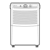
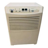
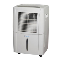
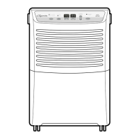
Describes the cabinet, controls, refrigerant circuit, and other key components of the HWW unit.
Explains the meaning of DANGER, WARNING, CAUTION, and NOTICE symbols used in the manual.
Guidelines for inspecting equipment upon delivery and proper storage methods.
Covers protecting the unit from damage and initial site preparation before installation.
Specifies indoor installation requirements and necessary service clearances for HWW units.
Outlines best practices for installing water supply and return piping, including valve and strainer placement.
Provides guidelines for load plumbing based on temperature variations and specific applications.
Explains how to configure low water temperature cutouts, especially when using antifreeze.
Details water quality parameters, scaling potential, and methods to prevent corrosion.
Addresses managing particulate size and velocity to prevent erosion and clogging in ground water systems.
Guides on selecting and sizing expansion tanks and pumps for ground water systems.
Describes the function and selection of water control valves and flow regulation techniques.
Covers site preparation, utility identification, and installation of ground loop piping.
Discusses antifreeze selection, concentration, and low temperature cutout settings for ground loops.
Emphasizes compliance with electrical codes and proper connection techniques for line voltage.
Explains how to connect incoming line voltage and switch between 208V and 230V operation.
Presents electrical data tables for different models, including voltage, current, and fuse/breaker ratings.
Describes how to use the CXM terminal strip for connecting 24VAC accessories to the unit.
Illustrates low voltage wiring for thermostats and CXM control boards for different HWW models.
Explains how to adjust low water temperature cutout settings using jumpers on the CXM board.
Details test mode, retry mode, and how to configure inputs for optimal system performance.
Covers setting temperature limits, alarm relay functions, and DIP switch selections for system setup.
Details anti-short cycle, random start, fault retry, and lockout modes to protect the compressor.
Covers high/low pressure switches and water coil low temperature limits that prevent damage.
Explains over/under voltage shutdowns and the UPS warning feature for system monitoring.
Addresses UPS warnings and how to detect swapped FP1/FP2 thermistors.
Explains how to use CXM diagnostics and the process for initial unit start-up.
Outlines environmental requirements and operating parameters suitable for initial unit commissioning.
Details critical checks for valves, wiring, transformer, water flow, and controls at the unit level.
Covers comprehensive checks for system water quality, flushing, cooling tower/boiler, and strainers.
Details maintenance procedures for heat exchangers, considering water quality and loop type.
Covers annual checks for compressors, cabinet cleaning, and maintaining refrigerant system integrity.
| Brand | Heat Controller |
|---|---|
| Model | R-410A |
| Category | Dehumidifier |
| Language | English |