W
waltonrichardAug 14, 2025
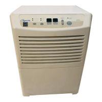
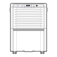
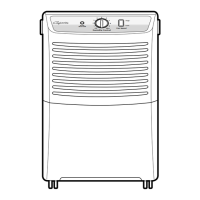
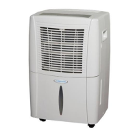
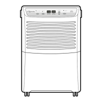
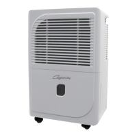
Why is my Heat Controller Dehumidifier so noisy?
- MMr. Justin MartinAug 14, 2025
If your Heat Controller Dehumidifier is operating noisily, check the following: 1. If the fan is cracked, out of balance, or partially missing, replace it. 2. Remove any loose foreign material inside the housing. 3. Carefully adjust the tubing if it's hitting the frame. 4. Check the motor mount; tighten it if the fan blade is hitting the frame. 5. If there is internal compressor noise, replace the compressor. 6. Tighten any loose set screws. 7. If the motor assembly has worn bearings and knocking sounds continue or the motor is loose, replace the motor. If the motor hums or the noise appears internal while running, replace the motor assembly.