Do you have a question about the Heat Surge X5C and is the answer not in the manual?
Lists essential tools for authorized technicians to perform service safely.
Provides key specifications including power, components, and physical dimensions.
Step-by-step guide to detach the front grill using mounting screws.
Instructions for removing the top cover, disconnecting cables, and handling safely.
Explains power input, circuit breaker, tip switch, and grounding.
Identifies AC-L3, AC-N4, and other power terminals on the main control board.
Details lamp specifications and the process for replacing bulbs in the bottom panel.
Steps to diagnose lamp issues by checking plugs and voltage at the control board.
A visual guide for troubleshooting non-functioning flame lamps.
Procedures for checking flame tube jams, fasteners, and bracket integrity.
Details on the flame tube motor's power, connection, and specifications.
How to test the flame tube motor plug and power supply voltage.
A flowchart for troubleshooting issues with the flame tube's rotation.
Testing blower function and identifying a sticky blower motor.
Verifying 120VAC supply to the blower motor terminals on the control board.
Explains how heating elements connect to the 750W terminals on the main board.
Details the connection of fusible link leads to AC-L1 and AC-L2 terminals.
Steps to detach the blower/heater assembly and the dual element heater.
A flowchart for diagnosing and resolving blower performance issues.
Procedure to test low heat and check 120VAC at the fusible link.
Guides for testing the fusible link and checking voltage at the control board.
Procedure to test high heat and check 120VAC at the control board terminals.
Steps to remove the dual element heater and install a new one.
Testing the touch pad for responsiveness and checking ribbon cable connections.
Identifying plug locations for thermocouple, temp pot, remote sensor, and touch pad.
Testing the temperature pot and ensuring its connection to the main control board.
Verifying the temperature sensor's connection and proper function.
Instructions for using the remote and checking battery orientation.
Checking the remote sensor plug and its physical placement behind the flame screen.
Steps to remove the front glass frame held by screws.
How to remove rubber plugs and screws to detach the log set.
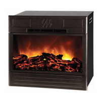
| Model | X5C |
|---|---|
| Type | Electric Fireplace |
| Heating Area | Up to 1000 sq ft |
| Voltage | 120V |
| Wattage | 1500W |
| Remote Control | Yes |
| Finish | Black |
| Heating Technology | Infrared Quartz |
| BTU | 5200 BTU |
| Safety Features | Overheat protection |
| Adjustable Thermostat | Yes |