(
)
Push
a knob
bushing
part
way
onto
each
of
the
four switch shafts.
Then
turneachof the
four shafts
to the
full
counterclockwise
position.
(
)
At
one
of
the
four switch locations, line up
the
pointer
of
a knob with
the
full
counter-
clockwise
marking
on
the
panel.Thenpress
the
knob slightly
onto
the lmob
bushing.
(
)
Turn
the knob clockwise
to each
of
the
switch
stop
positions.
Check to
see
that the
pointer
lines up
with each
panel
marking.
NOTE: Perform
the next three
steps
only
if
the
pointer
does
not
line
up at
each switch
marking.
1.
(
)
Turn
the larob
pointer
to a mid-position
marking
on
the
panel.
2.
(
)
Remove the
lsrob from
the
bushing and
turn
it slightly
to
line up
the
pointer
with the
mid-position
marking.
3.
(
)
Press
the knob
slightly onto
the knob
bushing.
Then turn the lmob to
each
switch
position
and recheck
thepointer
alignment.
ff
more than a
slight
error
is noticed at either endposition, repeat
these three
steps.
(
)
Carefully
remove the knob
bushingandknob
together.
(
)
P1ace
the knob
on
a tableorotherhard
sur-
face, then
press
the knobbushingfirmlyinto
the
knob. Use
a towel
or
soft
cloth on
the
work
surface to avoid
scratching
the knob.
(
)
Press
the
la:ob and
bushing firmly
onto
the
switch shaft.
(
)
nepeat the
above
I{nob
Installation
steps
to
install knobs
on
the remaining
switch shafts.
NOTE:
Each
of
the four
pointer
larobs is
now
made to
match the
panel
markings
at aparticular
location. If
it becomes necessary to
remove the
knobs at
any time,
be
sure to
replace
them
on
their
proper
shaJts.
Bottery lnstollotion
Before
you
install the
batteries in
your
Volt-
meter,
turn
all four
switch knobs fully
counter-
clockwise.
NOTE:
The
9-volt battery
is required for
port-
able
operation
of
the Voltmeter.
The
t-1/2 volt
battery
is
required
for the
Ohms function,
whether the
unit is
being
operated
from the
power
line or from
the
internal
9-volt
battery.
These
batteries are available
at
your
local radio
or
electronics
supply store.
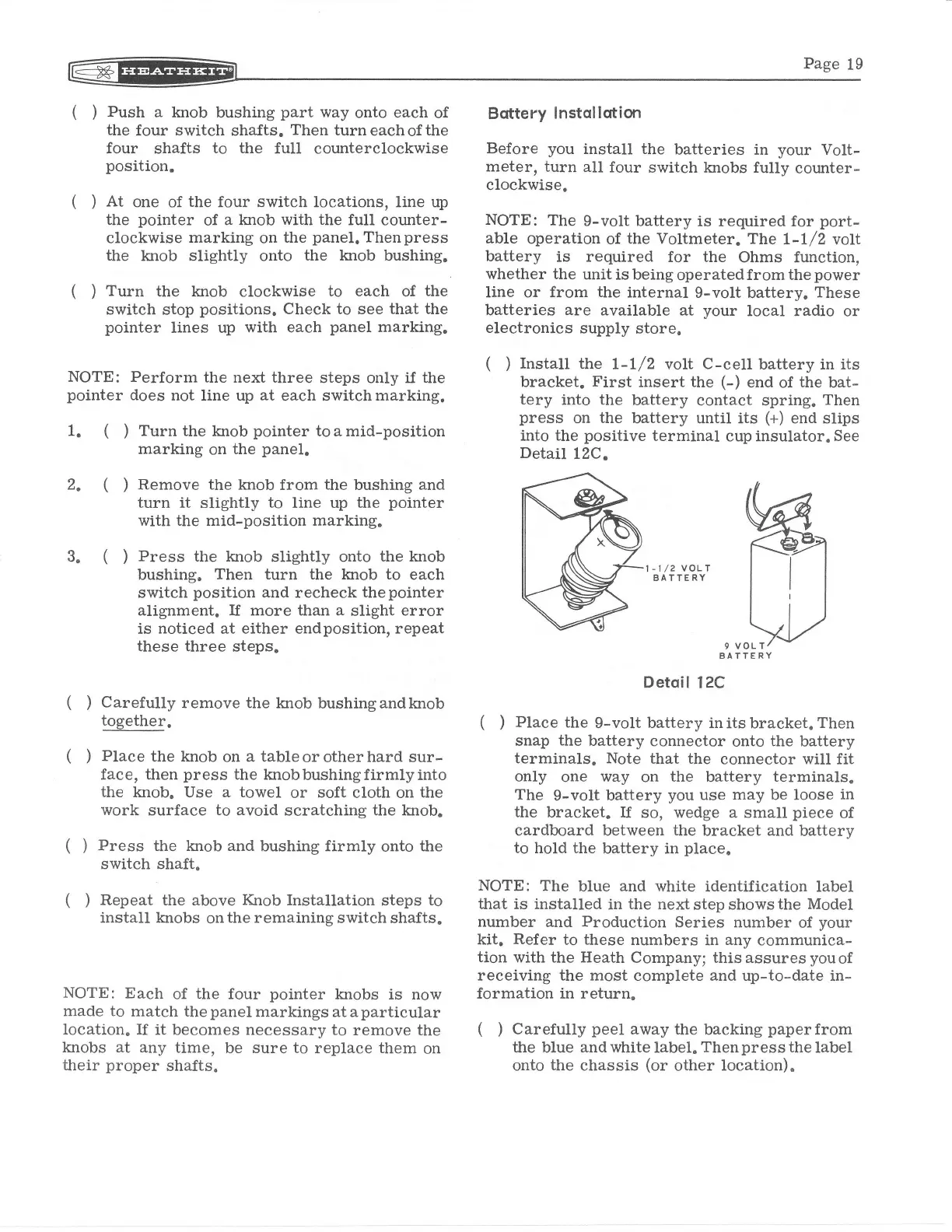
(
)
Install
the
L-L/2 volt
C-cell
battery
in its
bracket.
First
insert the
(-)
end of
the
bat-
tery
into the
battery
contact spring.
Then
press
on
the
battery until its
(+)
end
slips
into
the
positive
terminal
cup insulator,
See
Detail
12C.
l-ll2 voLT
AATTERY
9 VOLT
BATTERY
Detqil
l2C
(
)
Place
the
9-volt battery in its bracket.
Then
snap
the
battery
connector
onto
the
battery
terminals. Note
that the
connector
will fit
only
one
way
on
the
battery
terminals.
The
g-volt
battery
you
use
may
be loose
in
the
bracket. ff
so,
wedge a
small
piece
of
cardboard between
the
bracket
and
battery
to
hold
the
battery in
place"
NOTE:
The
blue
and white
identification label
that
is installed
in
the
next
step
shows the
Model
number
and
Production
Series number
of
your
kit.
Refer
to
these
numbers
in
any
communica-
tion with the Heath
Company; thisassuresyouof
receiving
the
most complete and up-to-date in-
formation in return.
(
)
Carefully
peel
away
the backing
paperfrom
the
blue
and
white labeI.
Thenpress the
label
onto
the
chassis
(or
other
location).
 Loading...


