Do you have a question about the Heathkit SW-717 and is the answer not in the manual?
Background on Heathkit's general coverage receivers and the SW-717's context.
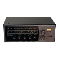
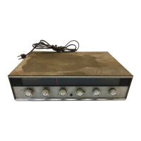
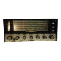
Physical description, dimensions, price history, and key specifications of the SW-717.
Explanation of the receiver's internal circuit design and a block diagram overview.
Analysis of the front end, IF stages, BFO, AGC, detector, audio amplifier, and power supply circuits.
Steps and considerations for assembling the SW-717 kit, including final testing procedures.
Discussion of typical issues encountered with the SW-717 and a concluding summary of its usability.
The Heathkit SW-717 is a general coverage communications receiver designed for shortwave listening. Advertised as a "Three Evening Kit," it was intended for beginners to assemble. The receiver covers the broadcast band and up to 30 MHz in four bands, allowing users to tune in to foreign broadcasts, weather reports, ships at sea, amateur and CB bands, and local AM entertainment.
The SW-717 is a superheterodyne receiver, a common design for its time. It features a built-in speaker and a front panel jack for headphones or an external speaker. The receiver operates on either 120 or 240 VAC (60/50 Hz) and draws 8 watts of power. Its primary function is to receive radio signals across a wide frequency range, with features like bandspread tuning for separating adjacent stations and a variable BFO (Beat Frequency Oscillator) for clear code reception. An automatic noise limiter (ANL) can be switched on or off to clip positive noise peaks, improving audio clarity in noisy conditions. The S-meter indicates relative signal strength.
The SW-717 lacks an RF amplifier. The input from the antenna is coupled by separate LC circuits for bands 'B' through 'D' directly to the mixer (Q2), an RCA 40673 dual-gate MOSFET. Band 'A' (broadcast band) uses a tuned ferrite rod antenna and is not connected to the external antenna connector. The HF oscillator (Q1) uses a Motorola MPF-105 JFET, with power regulated by a zener diode for stability. The IF operates at 455 KHz. The oscillator operates above the received frequency on bands A, B, and C, and below it on band D. Bandspread tuning only adjusts the oscillator frequency, which can lead to minor loss of sensitivity as input coils are not simultaneously tuned.
The IF signal passes through two 455 KHz ceramic filters in series before being amplified by a 2N5308 Darlington transistor (Q3) and a 2N5232A transistor (Q4). The output from the IF section is fed to the detector stage and the AGC amplifier.
The BFO circuit is unconventional, likely a cost-saving measure. Output from the third IF filter is fed back through a potentiometer to the input of the first ceramic filter. In AM mode, the BFO control is set to zero. For CW reception, advancing the BFO control causes the IF to oscillate at 455 KHz, allowing for tone adjustment by main or bandspread tuning. The BFO can also increase AM signal sensitivity through regeneration, but advancing it too far causes oscillation.
The AGC circuit rectifies and amplifies the IF signal via a 2N5232A transistor (Q5), producing a positive voltage dependent on signal strength. This voltage feeds a milliamp meter for relative signal strength. A pi R-C network filters the AGC output, providing a slow decay AGC voltage fed back to the bases of Q3 and Q4 to reduce gain on strong signals.
The MODE switch has three positions:
The detector is a simple diode circuit using a 1N191 crystal diode (D1). The recovered audio goes to the VOLUME control and audio amplifier. The ANL diode (D3) clips positive noise peaks.
The audio amplifier consists of four transistors (Q6-Q9). Q6 (NPN) drives Q7, which in turn drives complementary power transistors Q8 (NPN MPSU05) and Q9 (PNP MPSU55). Diode D2, a "Stabistor diode," prevents thermal runaway in the output transistors.
The power supply uses a transformer and a full-wave bridge rectifier. It provides 22 volts to the audio amplifier and 10 volts to the rest of the receiver. Two transistors (D9 and D10) act as zener diodes in the low-voltage supply, providing protection against power line spikes.