Do you have a question about the Heathkit GR-54 and is the answer not in the manual?
Details frequency ranges for different bands.
Specifies the rejection levels for image frequencies.
Defines the receiver's ability to distinguish signals.
Indicates the minimum signal level for reception.
Outlines voltage, frequency, and power consumption.
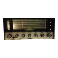
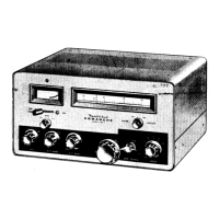
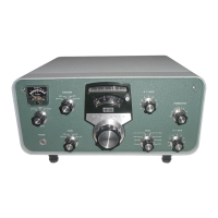
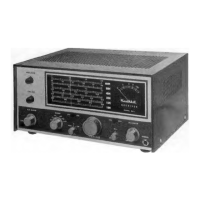
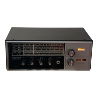
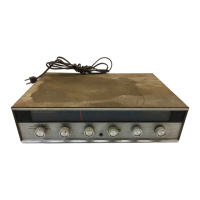
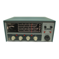
Lists and describes front panel controls.
Identifies rear panel connection points.
Provides physical size and weight specifications.
Describes signal mixing and initial amplification stages.
Explains intermediate frequency amplification and signal detection.
Details the audio amplification and output stages.
Covers the full-wave rectifier and filtering components.
Specifies front panel control positions for initial setup.
Describes steps for turning the receiver on.
Details initial control settings and tool preparation.
Provides step-by-step instructions for aligning coils using stations.
Sets front panel controls for BFO alignment.
Guides the adjustment of the BFO coil for zero beat.
Describes signal generator and VTVM connection and settings.
Details the procedure for aligning the receiver using test equipment.
Table listing signal generator frequencies and coil adjustments.
Adjusts coil for station indication on Band A.
Adjusts coil for station indication on Band B.
Adjusts coil for station indication on Band C.
Adjusts coil for station indication on Band D.
Adjusts coil for station indication on Band E.
Explains the function of each front panel control.
Identifies rear panel connection points.
Details AM, USB, LSB, and CW reception modes.
Describes long-wire, dipole, and inverted-V dipole antennas.
Instructions for setting up a long-wire antenna.
Steps for installing dipole and inverted-V dipole antennas.
Emphasizes checking connections and solder joints.
Advises checking parts values and tube functionality.
Lists problems like resistance readings and filament issues.
Covers distortion, hiss, and lack of signals.
Visual representation of the receiver's signal path.
Detailed circuit diagram showing all components and connections.
| Type | Communications Receiver |
|---|---|
| Modes | AM, CW, SSB |
| IF Frequency | 455 kHz |
| Frequency Range | 550 kHz to 30 MHz |
| Sensitivity | 1 μV for 10 dB S+N/N |
| Image Rejection | 40 dB |
| Audio Output | 2.5 watts |
| Power Supply | 50/60 Hz |