Do you have a question about the Heathkit Comanche MR-1 and is the answer not in the manual?
Specifies the receiver's intermediate frequency value.
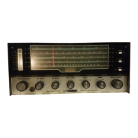
Details the amateur radio bands the receiver can tune.
Describes the crystal filter's bandwidth and characteristics.
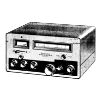
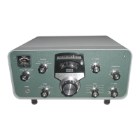
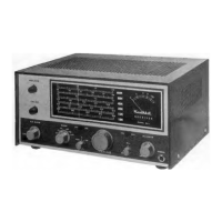
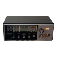
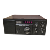
Lists the main controls available on the receiver's front panel.
Details the initial radio frequency amplification stage.
Explains the mixer and oscillator stage for frequency conversion.
Describes the intermediate frequency crystal filter's role in selectivity.
Details the first intermediate frequency amplification stage.
Describes the second IF stage and the S-meter amplifier.
Explains the stage for detection, audio amplification, AVC, and noise limiting.
Explains the product detector function for CW/SSB.
Details the stage responsible for audio output amplification.
Describes the circuit that stabilizes voltage for critical components.
Provides essential advice for successful soldering during assembly.
Details how to set the S-meter for accurate signal indication.
Specific calibration steps for the 10-meter band.
Specific calibration steps for the 15-meter band.
Specific calibration steps for the 20-meter band.
Specific calibration steps for the 40-meter band.
Specific calibration steps for the 80-meter band.
Calibration steps for the 3 mc product detector.
How to adjust the receiver's audio volume.
Describes the receiver's standby mode when used with a transmitter.
How to adjust the radio frequency gain.
Explains how the receiver's selectivity works and how to adjust it.
How to change between different frequency bands.
General notes on receiver calibration procedures.
How to adjust the antenna input for optimal reception.
How to use the noise limiter to reduce interference.
Explanation of the automatic volume control system.
How to select detection modes for different signal types.
How to adjust the beat frequency oscillator for CW/SSB.
Steps for tuning AM broadcast signals.
Steps for tuning single sideband signals.
Steps for tuning continuous wave signals.
Describes an accessory for monitoring battery charge.
Describes an accessory for charging batteries.
Describes an accessory for tuning transmitters.
| Type | Communications Receiver |
|---|---|
| Weight | 22 lbs |
| Modes | AM, CW |
| Sensitivity | 1 uV for 10 dB S/N |
| Selectivity | 2.1 kHz at -6 dB |
| Image Rejection | 60 dB |
| Audio Output | 1 Watt at 10% THD |
| Power Supply | 117 V AC, 50/60 Hz |