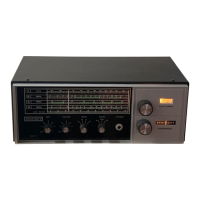
front panel starting at the left edge and ex-
tending from top to bottom. The dial has five
frequency bands, A through D and a LOG
scale marked 0 to 100. Band A goes from 550
to 1500 KHz, Band B from 1.5 to 4.0 MHz,
Band C from 4.0 to 10 MHz and Band D from
10 to 30 MHz. Below the actual dial marking
area four of the controls and the phone jack
pass through holes in the plate. They are
(left-to-right) BFO, VOLUME, BAND, MODE
and PHONES. To the right of the dial plate
and vertically spaced are the larger MAIN
TUNING (top) and BANDSPREAD knobs. To
the right and slightly above the MAIN TUNING
knob is the small SIGNAL meter. and to the
right and slightly above the BANDSPREAD
knob is the small band spread slide rule dial.
marked 5–0–5. The BFO is turned off by turn-
ing its control fully counterclockwise.
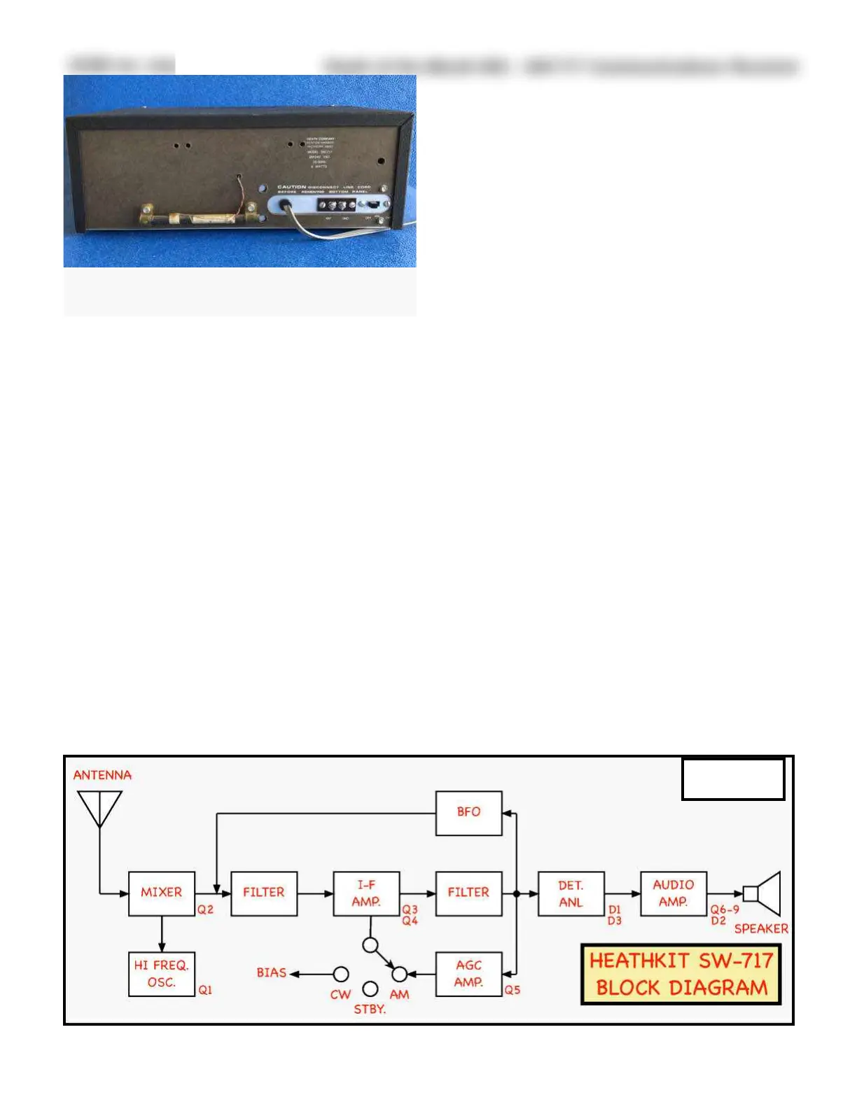
The rear panel (Figure 2) is rather barren.
Everything is located along the bottom edge.
From left to right (as viewed from behind) is
the ferrite rod antenna for the broadcast
band, the 3-wire AC power cord, a two screw-
type terminal strip marked ANT and GND
and a two-position slide switch marked OFF
ANL ON (automatic noise limiter).
The SW-717 has a built-in speaker located on
its right side-panel; an external speaker may
be plugged into the PHONES jack since it is
low impedance, taken directly off the inter-
nal speaker.
The SW-717 operates on 120/240 VAC 60/50
Hz. depending on how the transformer pri-
mary is wired. The instruction manual in-
cludes the necessary information should it
need to be changed. The receiver draws 8-
watts.
The SW-717 Circuit:
Superheterodyne receivers have been dis-
cussed in prior reviews so only the highlights
will be covered. Figure 3 is a simple block di-
agram of the SW-717, showing its simplicity.
Only the more unusual aspects of the circuits
will be covered in some detail. A schematic of
the SW-717 is available online
4
and a small-
er copy (Figure 9) is reproduced at the end of
this article.
 Loading...