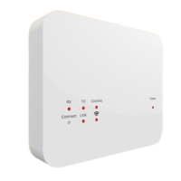
Boost – LED/button indication Installing the Boost
RF Repeater LED’s
(RX TX Comms)
Power
status
LED
Pairing buttons
Mesh Repeater
LED’s
(Link )
• Using a small screwdriver,
slightly loosen the screw
located at the base of
the Boost. You can then
carefully separate the front
panel from the back plate.
• Position the Boost back
plate on the wall, fixing
into place using the
screws provided.
• Terminate the cables to the
Boost as shown in the
wiring diagram (section 6).
• Mount the front panel onto
the back plate, tighten the
retaining screw on the base.
• Switch on the power
supply, the power LED
will illuminate.
Rev 1.0
Model: Boost
Want More Information?
PDF FAQ VIDEO
Call our support team on: +44 (0)1254 669090
Or view technical specifications directly on our website:
www.heatmiser.com
Twitter: @heatmiseruk Facebook: facebook.com/thermostats
1 2