9
2.2 Analog Values of the 1 V
PP
Incremental Signals A and B:
The transmitted values correspond to the values of the AD converter at the time of the trigger event.
Bit no. Width (bits) Contents
0..11 12 12-bit AD converter value
12..15 4 Reserved
Value (HEX) Incremental signal value
000 Negative maximum
800 Zero
FFF Positive maximum
2.3 Dealing with Reference Marks
With incremental encoders, the reference mark/marks is/are used to generate an absolute reference for the incremental
signals.
For encoders with one reference mark, this mark has an explicit reference to a specific signal period. This signal period can
be used as a reference to generate absolute position values. Traversing the reference mark does not affect the period
counter or the interpolation value. The period counter value valid at the time of traversing is simply saved in a register for the
reference position. This value can be used in the customer software application to calculate absolute position values.
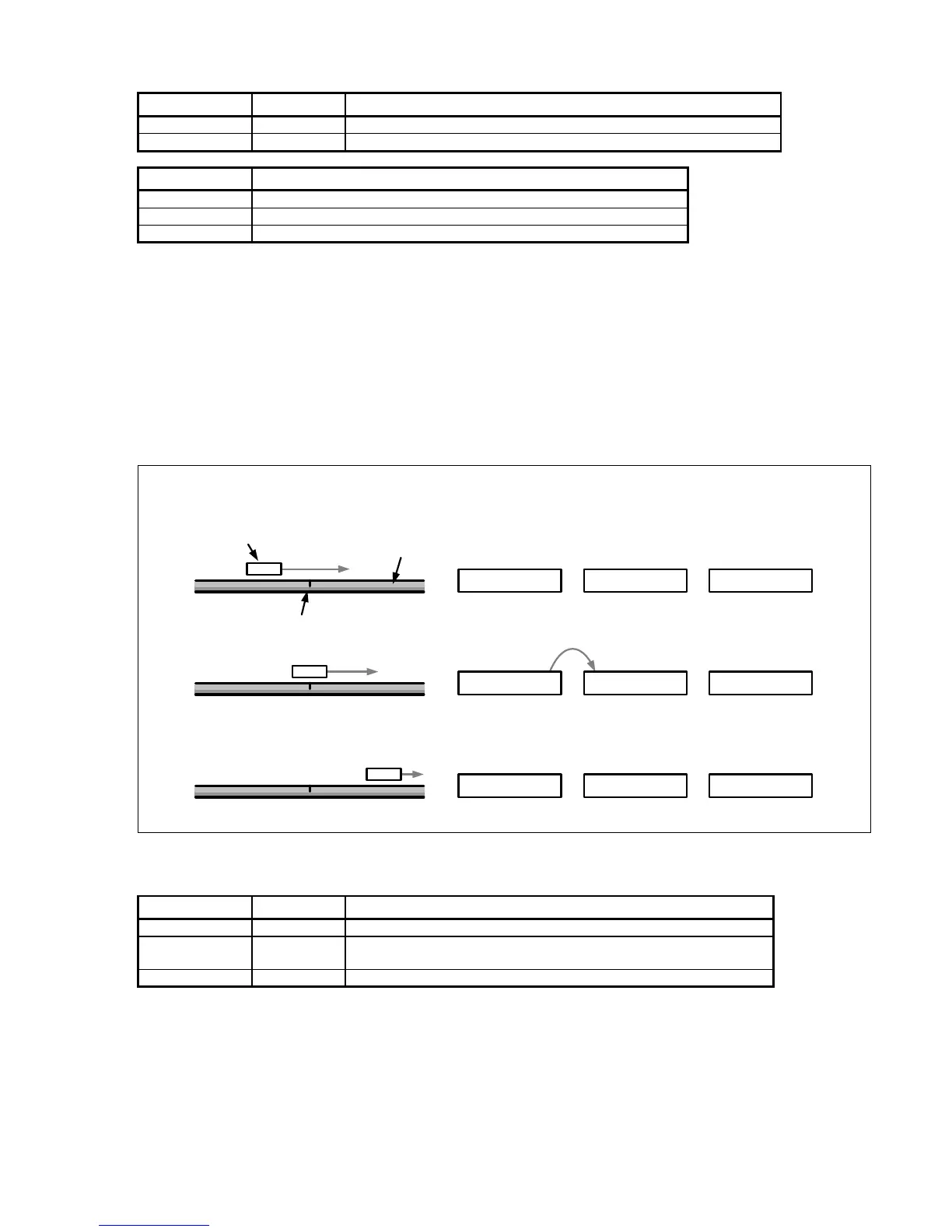
The figure below shows the general process of determining a reference position. The displayed values are only given as an
example. To improve clarity, only a section of the position-value register is shown.
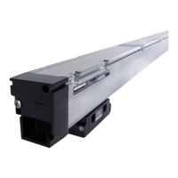
Linear scale
Scanning head
Reference mark
Motion
0x2A733D1
Actual position
value
Stored reference
position
Absolute position
(calculated by the
application)
0x318B000
0x36D9884
0x318B000
0x318B000
0x0000000
0x054E884
-
=
-
-
=
=
latch
Reference mark detected
Register contents, reference position
Bit no. Width (bits) Contents
0..11 12 Always 0
12..43 32
Reference position (value of the period counter when the reference
mark is detected; bit 43 = algebraic sign)
44..47 4 Value identical to bit 43
Automatic saving of the reference position must be activated by software. After this command, the EIB 74x waits for the
next reference mark and then saves the reference position.
You must activate this feature again if renewed saving is desired.
Normally, the reference position register is transmitted together with the position register and the status word in a shared
position data packet after the next trigger event. During this process, the EIB 74x transmits two reference positions and,
where applicable, the coded reference value:
• For encoders with one reference mark, reference position 1 is normally used.
• For encoders with distance-coded reference marks, either both register values are used or the coded reference
value is used depending on the evaluation method.
 Loading...