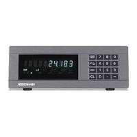
The HEIDENHAIN ND 281B is a measured value display unit, designed as a benchtop model, primarily for use with photoelectrical linear or angular encoders that provide sinusoidal signals, such as HEIDENHAIN MT length gauges. It processes 11 µApp sinusoidal current signals (via input X1) or 1 Vpp sinusoidal voltage signals (via input X2). The unit is shipped in linear measurement mode but can be switched to angular measurement mode using code number 41 52 63.
Function Description:
The ND 281B displays actual values with 9 decades and an algebraic sign. It features a numeric keypad with a decimal point for input and a status display with indicators.
Datum Setting:
The device allows setting two separate datum points. Datum setting can be done by entering a numerical value, transferring a value from operating parameters (P79, P80), or via an external signal. The display unit restores the relationship between length gauge position and display values when a reference mark is crossed, or when power is restored after an interruption. For distance-coded reference marks, a traverse of up to 20 mm (linear encoders) or 10°/20° (angle encoders) is sufficient to restore the datum.
Measurement Series (Linear Mode Only):
The ND 281B can perform series of measurements to find minimum (MIN), maximum (MAX), and difference (DIFF) values. After starting a series, the display compares the current measured value every 0.55 ms with stored MIN and MAX values, updating them if a new value is greater (MAX) or smaller (MIN). The difference (MAX-MIN) is also calculated and stored. The current measured value is indicated as ACTL. Measurement series can be started by pressing MOD or via an external signal (pin 6 on D-sub connection EXT X41). The internal MIN/MAX/DIFF memory is reset when a new series starts.
Sorting and Tolerance Checking:
In this mode, the display compares the measured value with programmed upper (P19 U.CLASS) and lower (P18 L.CLASS) sorting limits. The mode is enabled/disabled with parameter P17 CLASS. Indicators and switching outputs (X41) classify the display value into three categories: within limits (=), smaller than lower limit (<), or greater than upper limit (>).
Measured Value Output:
Measured values can be transmitted via the RS-232-C/V.24 interface (X31) to a printer or PC in ASCII format. Output can be initiated in linear mode by pressing MOD until PRINT blinks, then ENT. In angular mode, it's initiated by pressing MOD (can be disabled by P86). Alternatively, an STX command (Ctrl B) via RXD input (X31) or a pulse/contact signal at D-sub connection EXT (X41) can trigger output.
Display Freeze:
The display can be stopped for any period while the internal counter remains active. Parameter P23 DISPL. offers three settings:
- Concurrent display: No freeze, displays current measured value.
- Frozen display: Value is frozen and updated only with each signal for measured value output.
- Frozen/concurrent display: Display remains frozen as long as a latch signal is present; resumes continuous display after the signal.
Multipoint Axis Error Compensation:
This feature corrects nonlinear axis errors (e.g., axis sag, leadscrew errors). It requires activation via P40 COMP., traversing reference marks after switch-on, and entering a compensation value table. For linear encoders, up to 64 compensation points can be used; for angle encoders, up to 72 points (fixed spacing of 5 degrees). Compensation values are entered in millimeters for displayed compensation points. Compensation point 0 always has a value of 0.
Distance-to-Go Mode (Linear Mode Only):
Instead of the actual position, the display can show the remaining distance to an entered nominal position. This mode is accessed via code 24 65 82. In this mode, switching outputs A1 (pin 15) and A2 (pin 16) are symmetrical to the display value zero.
Locking the Keypad:
The keypad can be locked or released using code 24 65 84 (P00 CODE). When locked, only datum selection or P00 CODE via MOD key is possible.
Important Technical Specifications:
- Housing: Benchtop design, cast-metal housing (239 mm x 84.6 mm x 224 mm).
- Weight: Approx. 1.5 kg (3.3 lb).
- Operating Temperature: 0° to 45° C (32° to 113° F).
- Storage Temperature: -20° C to 70° C (-4° F to 158° F).
- Relative Humidity: < 75% annual average, < 90% in rare cases.
- Power Supply: Primary-clocked, 100 Vac to 240 Vac (-15% to +10%), 50 Hz to 60 Hz (± 2 Hz).
- Line Fuse: F 1 A (inside housing).
- Power Consumption: 8 W (typically).
- Electromagnetic Compatibility: Class B according to EN 55022.
- Noise Immunity: Per VDE 0843 Parts 2 and 4, severity 4.
- Protection: IP40 according to IEC 529.
- Display Step: Adjustable.
- Datum Points: Two.
- X1 (9-pin HEIDENHAIN flange socket): For 11 µApp sinusoidal output signals. Max. 100 kHz input frequency, 30 m cable length.
- X2 (12-pin HEIDENHAIN flange socket): For 1 Vpp sinusoidal output signals. Max. 500 kHz input frequency, 60 m cable length.
- Reference Mark Evaluation: For distance-coded and single reference marks.
RS-232-C/V.24 Data Interface (X31):
- Baud Rates: 110, 150, 300, 600, 1200, 2400, 4800, 9600, 19 200, 38 400 baud.
- Data Format: 1 start bit, 7 data bits, even parity bit, 2 stop bits.
- Maximum Cable Length: 20 m (66 ft).
- Inputs: 0 V, reset display to zero, set display to P79 value, ignore reference marks, start series of measurements, select display value for series (MIN/MAX/DIFF), transmit measured value (pulse/contact), enable/disable REF mode.
- Outputs: Display value is zero, measured value ≥ trigger limit A1 (P62), measured value ≥ trigger limit A2 (P63), measured value < lower sorting limit (P18), measured value > upper sorting limit (P19), error signal.
- Signal Levels: High (+3.9 V to +15 V input, ≤ +32 V output), Low (-0.5 V to +0.9 V input, ≤ +0.4 V output).
- Minimum Pulse Duration: ≥ 30 ms for inputs.
- Delay for Set/Zero Reset: ≤ 2 ms.
- Delay until Signal Output: ≤ 30 ms.
- Signal Duration of Zero Signal/Trigger Limit: ≥ 180 ms.
Usage Features:
- User Parameters: P00 to P30, P50, P51, P79, P86, P98 can be changed without a code number.
- Protected Operating Parameters: Accessed by entering code 9 51 48 (P00 CODE).
- Language Selection: Parameter P98 LANGUA. allows selection of conversational language (German, English, French, Italian, Dutch, Spanish, Danish, Swedish, Finnish, Czech, Polish, Hungarian, Portuguese).
- Display Mode: P08 DISPL. (angular mode only) allows selection between decimal degrees (DEC. DEGREE) and degrees, minutes, seconds (DEG.MIN.SEC.).
- Units of Measurement: P01 (linear mode only) allows selection between millimeters (MM) and inches (INCH).
- Counting Direction: P30 DIR allows setting positive (DIRECT. POS) or negative (DIRECT. NEG) counting direction.
- Decimal Places: P38 DEC. allows selection from 1 to 6 decimal places (up to 8 for inch display), depending on signal period and unit of measure.
- Software Version Display: Code 66 55 44 (P00 CODE) displays the software number and date of issue.
- Data Transfer Function: Code 48 61 53 (P00 CODE) enables input/output of parameter and compensation-value lists via RS-232-C/V.24 interface.
Maintenance Features:
- Error Messages: The display unit shows error messages for various issues like RS232 FAST (output too quick), SIGNAL (encoder signal weak), DSR.MISSING (connected device not sending DSR), REF. ERR. (reference mark spacing incorrect), FORMAT ERR. (data format mismatch), FREQUENCY (input frequency too high), MEMORY ERR. (checksum error). "OVERFLOW" indicates a value too large/small. All sorting signals lit up indicates upper sorting limit is smaller than lower limit.
- Clearing Error Messages: Most error messages can be cleared with the CL key after the cause is removed.
- Internal Components: Danger to internal components if inductive loads are not connected with a quenching diode parallel to the inductance.
- Grounding: To increase noise immunity, connect the ground terminal on the rear panel to the central ground point of the machine (minimum cross-section: 6 mm²).
- Shielded Cables: Only use shielded cables for D-sub connections.