The synchromesh mechanism consists primarily of synchromesh cones, block
rings and inserts.
(1) Synchromesh cone
The gear (11) or (13) has a male cone, i.e. synchromesh cone mating with the
block ring (2) through respective cone friction surface, and an involute spline (3)
engaged with mesh sleeve spline (6).
(2) Block ring
The block ring has a female cone friction surface mating with the male cone’s of
the synchromesh cone and three notches on its circumference to align the spline of
mesh sleeve with block ring’s so that the mesh sleeve spline (6) is to be pressed
toward the block ring spline (1).
(3) Inserter
There are three inserters included. Their center projections are fitted in the inner
annular groove of the mesh sleeve spline, respective two ends in three notches of the
block ring. These inserters are pressed against the top of mesh sleeve spline by two
springs (8) to keep the block ring in position.
The operation of synchromesh mechanism is completed in six steps below (take
the gear (11) for example).
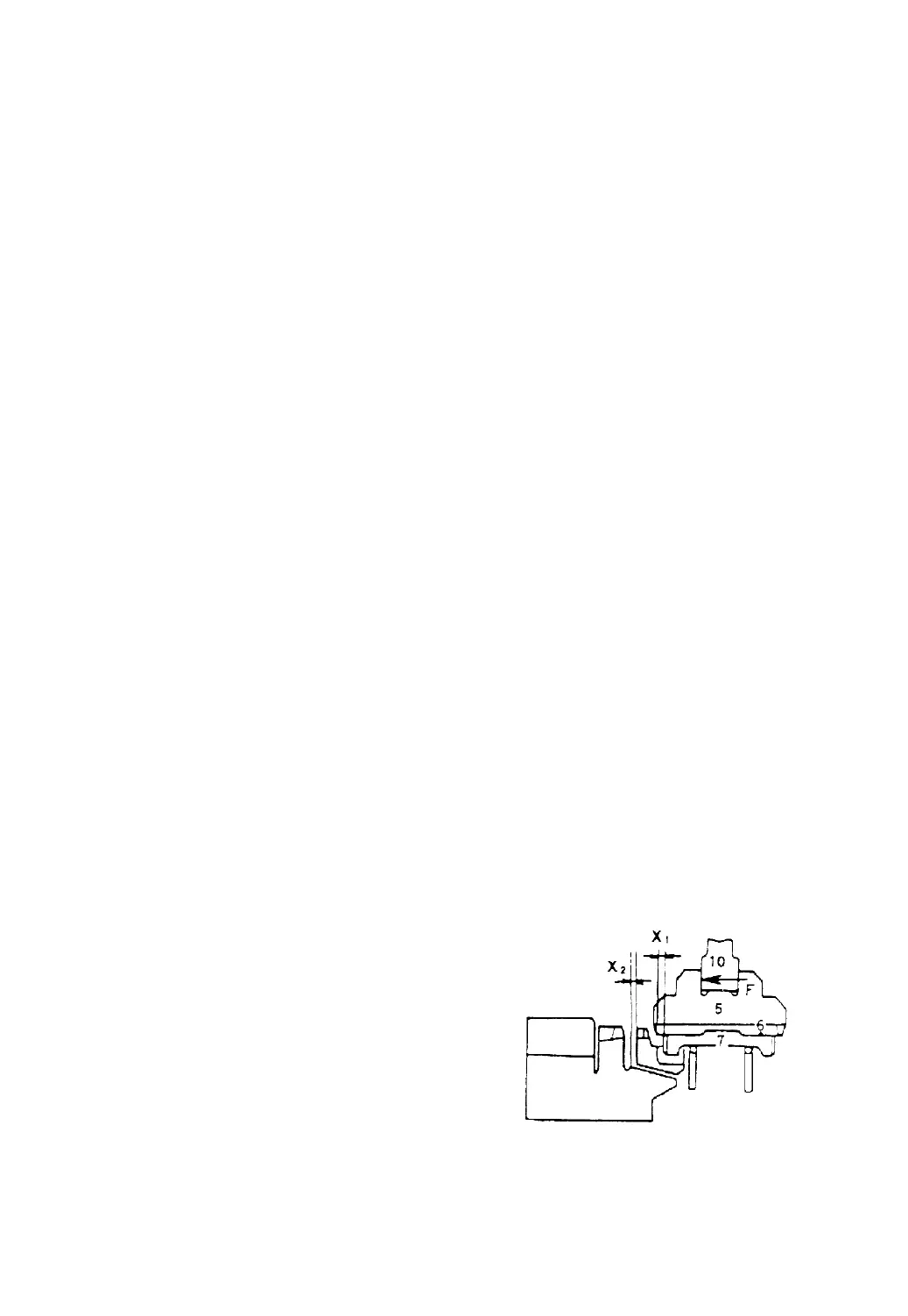
1st Step (See Fig.3-4)
When the force is applied on the shift
lever, it is transmitted to the mesh sleeve (5)
through the shift fork and then makes the
mesh sleeve (5) and inserters (7) axially move
toward the gear (11) by X and X
1 2
respectively. In this time, the center
projections of inserters (7) are still in the
groove of mesh sleeve spline.
Fig. 3-4
-21-
 Loading...