EN EN
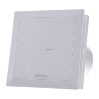
MultiVent
®
– MV EC
Installation and Operating Instructions
5
A B C D
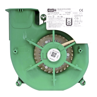
Dimensions (mm)
MV EC 100 60 80 5,5
MV EC 125 60 80 5,5
MV EC 150 60 80 5,5
MV EC 160 60 80 5,5
MV EC 200 155 280 120 5,5
MV EC 250 170 174,5 70 6,5
MV EC 315 255 259,5 110 8,5
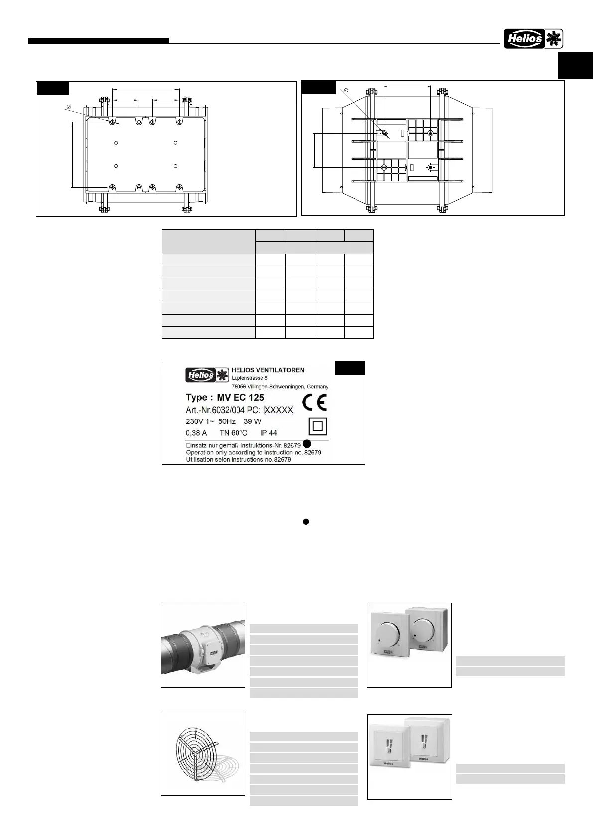
3�3 Type plate
Example:
Fan type plate key:
Ref. no. and PC (production code) numbers clearly identify the fan.
3�4 Accessories
The use of accessory parts, which are not recommended or oered by Helios, is not permitted. Any possible dama-
ges are not covered by the warranty. Other accessories see catalogue or www.heliosselect.de.
B
C C
A
D
Fig�10
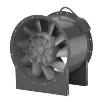
MV EC 200
MV EC 250
MV EC 315
A
D
Fig�11
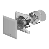
MV EC 100
MV EC 125
MV EC 150
MV EC 160
ù
ä
ë
ü
ö
Å
î
Ø
Æ
ò
Fig�12
11
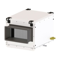
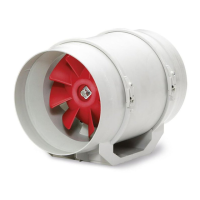
FM – Flexible sleeve
Description see main catalogue
FM 100 Ref. no. 1681
FM 125 Ref. no. 1682
FM 150 Ref. no. 1683
FM 160 Ref. no. 1684
FM 200 Ref. no. 1670
FM 250 Ref. no. 1672
FM 315 Ref. no. 1674
MVS – Protection guard
Description see main catalogue
MVS 100 Ref. no. 6071
MVS 125 Ref. no. 6072
MVS 150 Ref. no. 6073
MVS 160 Ref. no. 6074
MVS 200 Ref. no. 6075
MVS 250 Ref. no. 6076
MVS 315 Ref. no. 6077
PU/A 10
Speed potentiometer
For direct control/setpoint spe-
cification of EC fans with poten-
tiometer input.
PU 10 Ref. no. 1734
PA 10 Ref. no. 1735
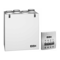
SU/A-3
Three-step switch
For three-step control of EC
fans with a 0-10 V DC control
input.
SU-3 10 Ref. no. 4266
SA-3 10 Ref. no. 4267
ò Manufacturer‘s address
ù Fan marking:
CE = CE mark
ä Version:
MV EC = Type designation
125 = Size
ë Ref. no.
ö Production code / Year of constr.
ü Rated voltage or voltage range / frequency
Å Rated current
î Power input
Ø max. air flow temperature at rated operation
Æ Protection class
Installation and operating instructions print no.
11
 Loading...