EN EN
MultiVent
®
– MV EC
Installation and Operating Instructions
4
If the temperature monitoring system trips frequently, this is a sign that a possible fault has occurred� The sys-
tem must not be operated and it must be investigated by a qualified electrician�
2�11 Condensation
In case of periodical use, moist and warm media and through temperature variations (intermittent service), condensate
is built up in the duct and its draining o must be ensured. In case of condensation in ducting and casing of the fan,
appropriate measures must be taken (water bag, drainage) during installation. Under no circumstances must the motor
be exposed to water.
3�1 Overview
The units are supplied with a potentiometer in a polybag for setting the control voltage as standard. This allows any fan
speed to be set between min. and max. speed. If required, it must be installed in the terminal box (see wiring diagram
„6.3.1 Standard wiring diagrams with PU/A 10“ auf Seite 11).
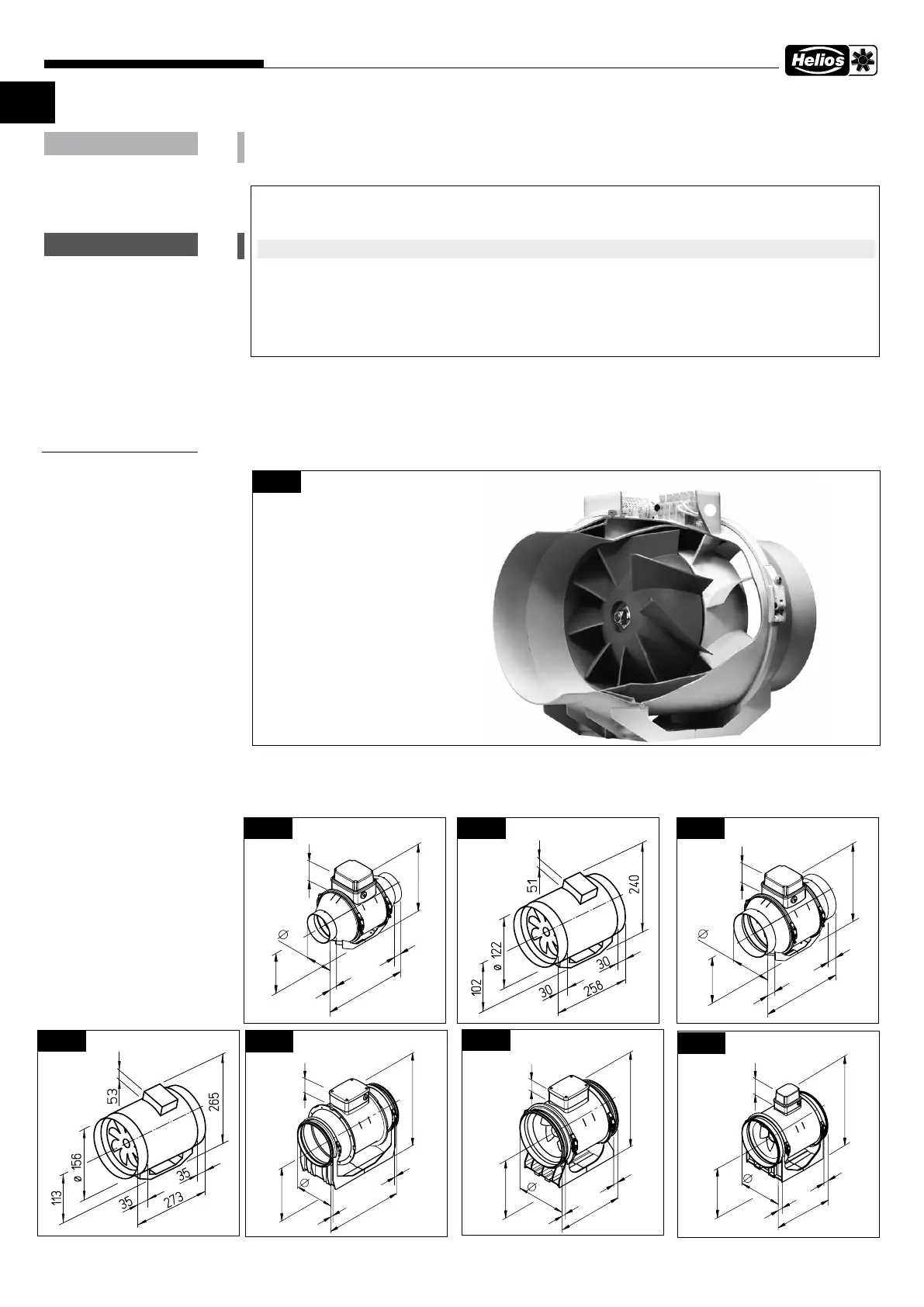
3�2 Dimensions (Dimensions in mm)
ATTENTION
Control of several EC-fans with a potentiometer
In order to control several EC fans via the setpoint input “0-10V”, the 10 V DC voltage source must provide the
sum of all setpoint input load currents.
m
Parallel connection of +10 V DC supply of several EC fans is not permitted!
Depending on the type several EC-fans can be controlled with the 10 V DC power supply from a fan with a poten-
tiometer (PU/A). For this see the technical data of the control inputs and the wiring diagram SS-1035.
If the power of the EC-supply is not sucient a customer-supplied sucient external 10 V DC can be used (gal-
vanically separated from the mains). Alternatively the Helios module “EUR EC“ can be used for various control
duties. The control cable must have the same insulation level as the mains cable.
m
WARNUNG
CHAPTER 3
TECHNICAL DATA
öö
üü
òò
ää
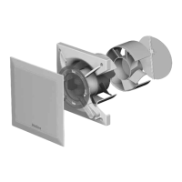
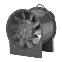
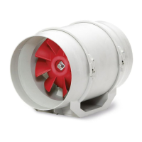
ò Casing made of impact and
corrosion-resistant polymer
ù High-performance impeller and
ä Guide vane made of polymer optimised
for high pressure and volume output
ë Terminal box on outside of casing
in IP45
ö Integrated mounting bracket for
mounting to wall and ceiling
ü Clamp with screw connection
Fig�2
ëë
Fig: Section view
ùù
96
58
303
30
30
240
102
Fig�3
MV EC 100
Fig�4
MV EC 125
146
265
58
35
35
294
113
Fig�5
MV EC 150
Fig�6
MV EC 160
198
396
15
15
373
195
75
Fig�7
MV EC 200
247
76
322
23
23
378
190
Fig�8
MV EC 250
311
307,02
419,3
39,61
506
134,42
223,8
506
135
224
420
40
40
Fig�9
MV EC 315
 Loading...