EN EN
MultiVent
®
– MV EC
Installation and Operating Instructions
11
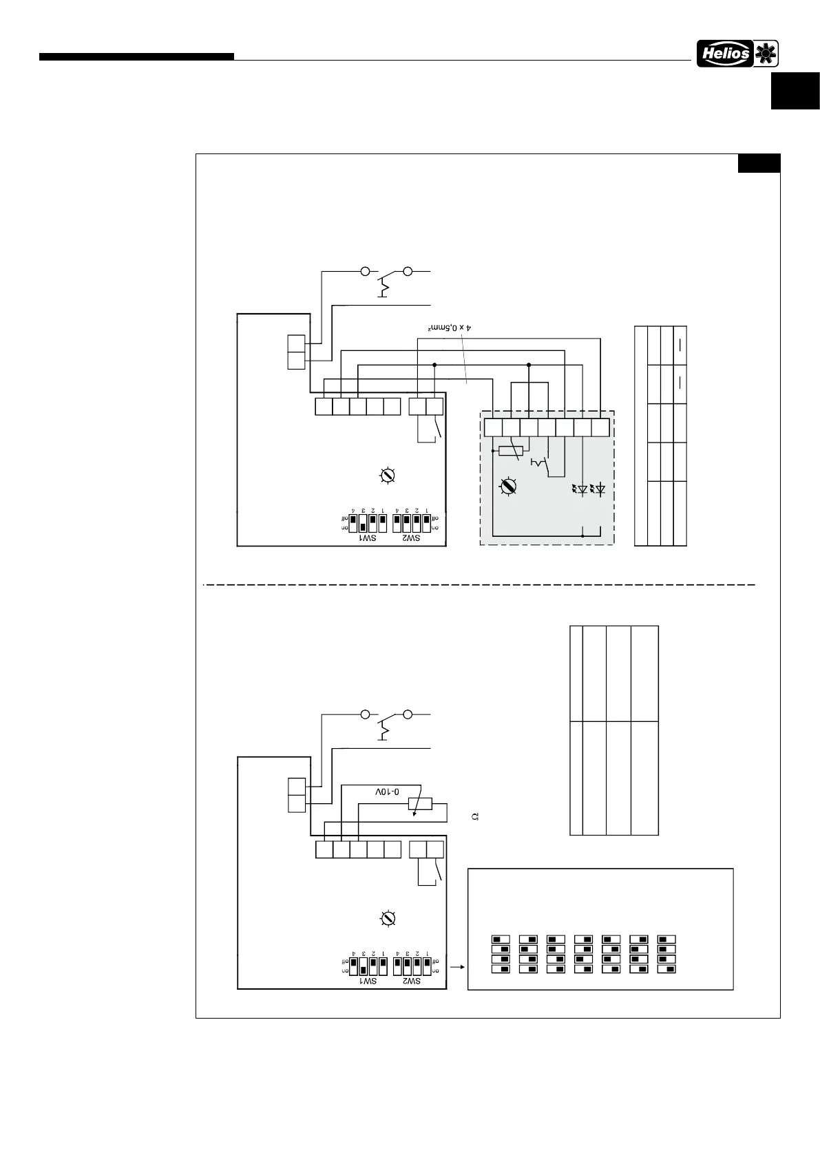
6�3�1 Standard wiring diagrams with PU/A 10
SS-1194
MV EC 100
MV EC 125
MV EC 150
MV EC 160
MV EC 200
MV EC 250
Alternating current,
1~, 230 V, 50 Hz
with PU/A 10
250 V
3A
NL
S2
S1
P0
PI
P10
+10V
0-10 V
GND
P1
MV EC 100 - 250 + PU/A 10
85459 001 SS-1194 08.06.20 S.2
R1
R2
3
2
4
PU/A 10
1
Potentiometer min.
rotational speed
7
6
5
LED 1
LED 2
S 1
R 1
Art.Nr. 1734/1735
1)
2)
3)
250 V
3A
NL
S2
S1
P0
PI
P10
+10V
0-10 V
GND
P1
MV EC 100 - 250 connection
LN
R1
R2
1)
2)
3)
LED display logic
terminal 6
10 V
10 V
0 V
0 V
terminal 7
0 V
10 V
10 V
0 V
LED display
red (1)
green (2)
10k
0-10V signal from e.g.
PU/A 10 Art.Nr. 1734/1735
or EUR EC Art.Nr. 1347
Potentiometer or rather
LN
1) device type (SW1)
1
off
on
2 3 4
1
off
on
2 3 4
1
off
on
2 3 4
1
off
on
2 3 4
1
off
on
2 3 4
MV EC 125
MV EC 160
MV EC 200
MV EC 250
MV EC 315
2) factory setting
(0-10V control voltage)
3) factory setting
4) with setpoint setting and without fault signal
5) without setpoint setting or with fault signal
Fan without mains supply
Fan with mains supply,
fan rotates
4)
relay contact R1-R2
open
closed
fan status
Fan with mains supply,
Fan stopped
5)
open
Isolation switch
to be provided by
customer
Isolation switch
to be provided by
customer
1
off
on
2 3 4
MV EC 100
1
off
on
2 3 4
MV EC 150
Fig�24
 Loading...