EN EN
MultiVent
®
– MV EC
Installation and Operating Instructions
10
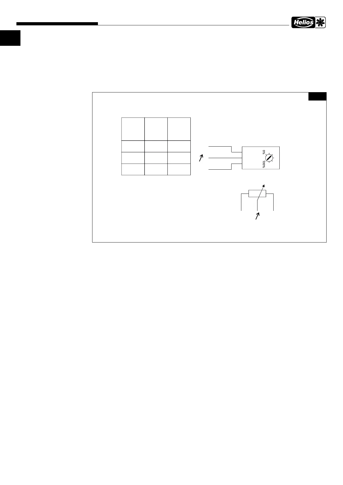
6�3 Wiring diagram overview
The units are supplied with a potentiometer in a polybag, which can be used to set the control voltage and thus set any speed
between min. and max. speed, as standard. If required, it must be connected.
For an external speed setting with a 0-10
V control signal, the internal potentiometer must be removed. The diagrams show the potentiometer in principle. It is
possible to connect an internal or external potentiometer
Potentiometer included
Fig�23
SS-1482
85499 2 SS-14 . .20285 82 01 03 3
Farbcode/color code
code couleur (IEC 757)
RD-rt-rot-red-rouge
YE-ge-gelb-yellow-jaune
WH-ws-weiß-white-blanc
rt
ge
ws
+
-
rt
ge ws
+
-
Hinweis:
KR... EC
RR EC
SV... EC
...
GBD EC
MBD EC
MV EC
...
HQW EC
HWW EC
HQD EC
...
10V
ADJ
GND
10V
0-10V
GND
10V
E1
GND
No additional voltage, either
potentiometer or 0-10V external
Pas de tension supplémentaire,
ni potentiomètre ni 0-10V externe
Keine zusätzliche Spannung, entweder
Potentiometer oder 0-10V extern
Beschriftung der Anschlussklemmen vom Gerät abhängig, z.B.
Labeling of the connection terminals depends on the device, e.g.
Le repérage des bornes de raccordement dépend de l'appareil, par ex.
 Loading...