EN EN
MultiVent
®
– MV EC
Installation and Operating Instructions
9
m
Activation / deactivation:
Frequent switching on and o of EC fans can be carried out via the 0-10 V control input by switching o the
control signal to 0 V� This applies to operation with an external potentiometer or external 0-10 V signal from
the building management system� Switching o is alternatively also possible via a release input, depending
on the type� This is gentle on the electronics and ensures a long service life� If this is not easy to realise,
e�g� when operating with an internal potentiometer, it can also be done by switching o the mains supply�
In general, a time interval of at least 120 seconds must be observed when switching the mains o/on�
m
In case of strong vibrations and/or noises, maintenance must be carried out by a specialist according to
chapter 1�5�
The use of other brands, especially other electronic devices, can lead to malfunctioning and even destruction
of controller and/or fan� Controllers which have not been cleared by Helios are not liable for warranty and gua-
rantee claims�
6�2 Speed control
– Power control with potentiometer supplied as standard
For continuously variable and direct control or setpoint specification. The setpoint signal must be specified by means of
an internal potentiometer or external control signal.
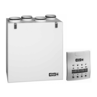
– Speed control with speed potentiometer PU/A
For variable and direct control or nominal value preset of EC fans with potentiometer input. Additionally equipped with
an enabling switch and LED-display for the operating status (dependant on feature of fan type). The potentiometer is
attached directly to the potentiometer input of the fan control system. This has therefore a potentiometer supply of e.g.
10 V DC and an input control signal of 0-10 V DC.
Basic circuit diagram:
Example: Variable speed control
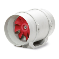
– Speed control with universal control system EUR EC
For variable control or adjustment of single and three-phase EC fans with an input control signal of 0 - 10 V DC.
Connection examples of the basic diagram are mentioned further below.
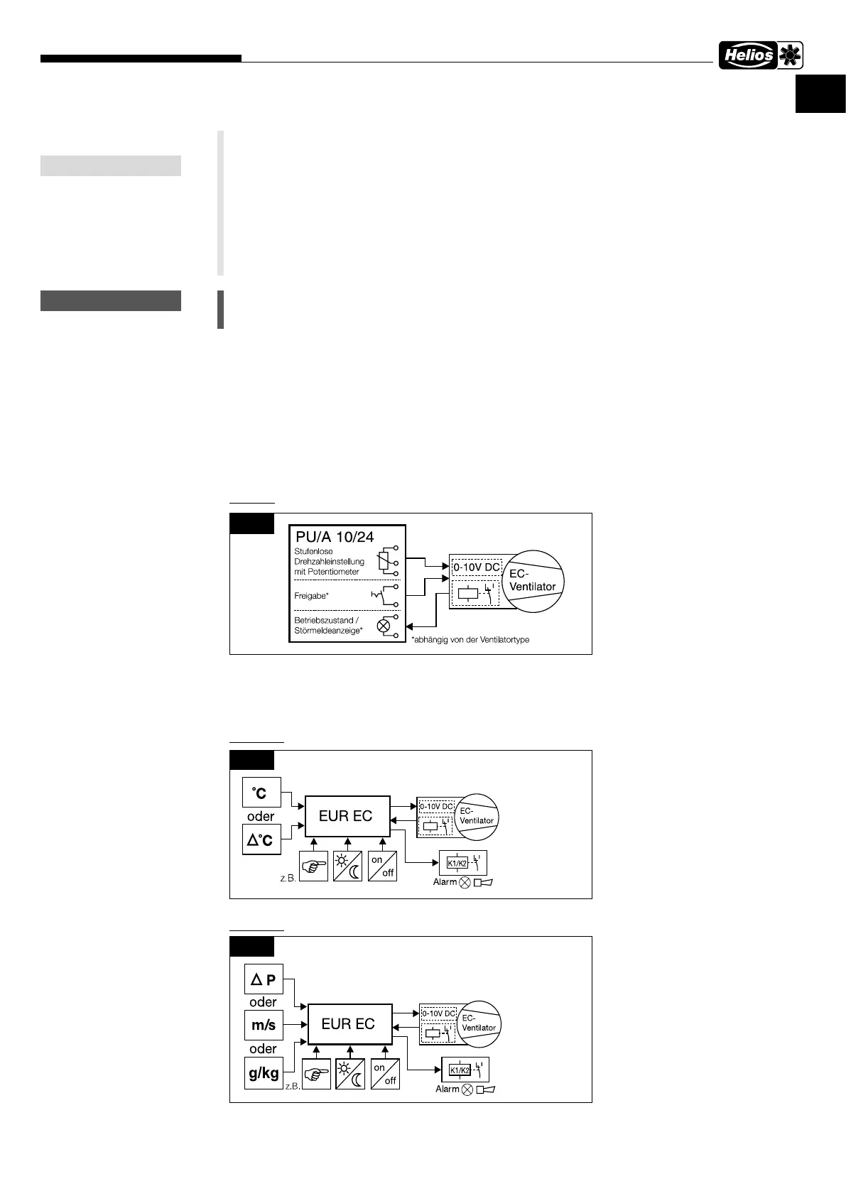
Basic circuit diagram:
Example 1: Temperature control with additional function and dierential temperature control
Example 2: Dierential pressure control and air velocity control
NOTE
m
WARNING
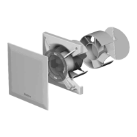
Fig�20
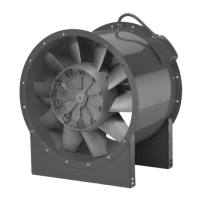
Fig�21
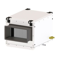
Fig�22
 Loading...