EN EN
MultiVent
®
– MV EC
Installation and Operating Instructions
8
The MultiVent
®
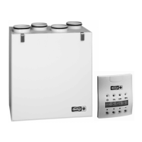
EC fans must be connected to the duct system using flexible sleeves (see Fig.18). For this purpose, e.g.
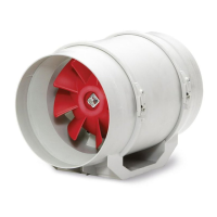
for installation in ducting, use a flexible sleeve FM (accessories) or an elastic underlayer between the mounting surface
and mounting bracket (Fig.19).
5�4 Electrical connection / Commissioning
m
Danger to life due to electric shock!
Touching live parts will lead to electric shock�
Isolate the unit from the mains power supply before connection!
When using capacitors, there is danger to life after deactivation due to the direct touching of live parts� Termi-
nal compartment access is only permitted after power supply is disconnected and 5-minute waiting period�
m
Risk of injury!
The rotating impeller can crush fingers�
Ensure protection against contact before commissioning!
m
Material damage due to improper installation of the control cable!
The mains cable must always be installed separately from the control cable�
If this is not possible, a cable with the insulation level of the 230 V mains cable must be used for the control
cable�
– The electrical connection and initial commissioning must only be carried out by qualified electricians
according to the information in the attached wiring diagrams�
– All relevant standards, safety regulations (e.g. DIN VDE 0100), as well as the technical connection conditions of
energy suppliers are to be adhered to!
– An all-pole mains section switch/isolator, with a minimum contact opening of 3 mm (VDE 0700 T1 7.12.2 / EN
60335-1) is mandatory!
– Network configuration, voltage and frequency must be consistent with the rating plate information.
– Check the waterproofing of the connection cable and tight clamping of the strands.
– Metal cable screws must not be used when connecting to plastic terminal boxes.
– Insert the supply cable so that no water can get in along the cable in case of water exposure. Never place the cable
over sharp edges.
– Check designated use of fan
– Check fan for solid mounting and professional electrical installation
– Check all parts for tightness, particularly screws, nuts, protection guards. Do not loosen screws in the process!
– If required, connect the potentiometer (supplied in polybag) or alternative external control device.
– Check free movement of the impeller.
Wear protective gloves when checking unhindered running of impeller!
– When the impeller is turned by hand, there will be slight resistance due to the permanent magnets. This is for
technical reasons and it is not a malfunction.
If a residual current circuit breaker is installed in the supply line of the KWL unit, the residual current circuit breaker
must have the following technical features:
Type A or B with a rated dierential current of 30 mA�
The EC fan has a leakage current of <= 3,5 mA, calculated according to DIN EN 50178 image 4.
5�5 Operation
In order to ensure the proper functioning of the fan, the following must be checked regularly:
– Formation of dust or dirt deposits in the casing or on the motor and impeller
– Freewheeling of impeller. Wear protective gloves when checking freewheeling of impeller!
– Occurrence of excessive vibration and noise
If excessive vibration or noise occurs, maintenance must be carried out according to the instructions in CHAPTER 7.
6�1 Functional description
The units are supplied with a potentiometer in a polybag for setting the control voltage as standard. This potentiometer
can be connected if required. This allows any fan speed to be set between min. and max. speed.
Alternatively, the potentiometers (type PU/A 10) and three step switches (type SU/A) from the Helios accessory range
can be used. The universal control system (type EUR EC) or the electronic dierential pressure/temperature controller
EDR / ETR can be used for sensor-controlled speed regulation.
Fig�18
Flexible sleeve FM
Fig�19
Mounting to the wall with
elastic underlayer
m
DANGER
m
WARNING
nmr
m
WARNING
m
WARNING
n
m
WARNING
n
CHAPTER 6
FUNCTION FOR
INSTALLER
 Loading...